
User manual
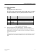
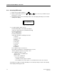
Table Of Contents
- Title Page
- Preface
- Section 1-Safety & Regulatory.pdf
- Section 2-System.pdf
- Section 2
- System Description
- Table of Contents
- chapter1.pdf
- chapter2.pdf
- Chapter 2
- System Overview
- 2.1 Operational Concepts
- 2.2 Roaming and Handover Handling by the Portable Telephone
- 2.2.1 Unlocked Situation
- 2.2.2 Locked Situation
- 2.3 User Functions
- 2.3.1 DCT1900 Mobility Configuration and E1-CAS Standalone when connected to a MD110
- 2.3.2 Standalone Digital Line Interface
- 2.3.3 Standalone Analog Interface and T1 CAS Digital Interface
- chapter3.pdf
- Chapter 4
- 4.1. General
- 4.2 Central Processing Unit-CPU1
- 4.3 Speech Link Unit - SLU
- 4.4 Speech Processing Unit -SPU-S
- 4.5 Cell Link Unit - CLU or CLU-S
- 4.6 Digital Trunk Unit
- 4.6.1 CCS
- 4.6.2 CAS
- 4.7 DTU-T1 CAS
- 4.8 DTU-T1 CCS
- 4.9 Line Termination Unit -LTU
- 4.10 Digital Line Unit
- 4.11 DLU AWS1024
- 4.12 DLU AWS1025
- 4.13 DLU AWS1026
- 4.14 Modular Cabinet Connection Board
- 4.15 Synchronization DistributionBoard
- chapter5.pdf
- Section 3-Product Specifications.pdf
- Section 3
- Product Specifications
- Table of Contents
- Chapter 1
- chapter2.pdf
- chapter3.pdf
- Chapter 3
- Batteries
- 3.1 Batteries for the DT600
- 3.1.1 High Capacity NiMH - BKB 193 1021
- 3.1.2 Vibrating Battery, NiMH - BKB 191 312
- 3.2 Batteries for the DT620
- 3.2.1 High Capacity NiMH Battery - BKB 193 104/75
- 3.2.2 Ultra-Slim Line NiMH Battery - BKB 193 105/75
- 3.3 Batteries for the 9p23
- 3.3.1 Messenger Battery - 643100
- 3.3.2 Messenger Battery with headset connection- 643101
- 3.3.3 Medic Battery - 643102
- 3.3.4 Medic Battery with headset connection- 643103
- chapter4.pdf
- Chapter 4
- Chargers
- 4.1 Chargers for the DT600
- 4.1.1 Desk Multi-Charger Kit - NTM 201 2022
- 4.1.2 Rapid Battery Charger Kit - BML 162 1016/72 Discontinued
- 4.1.3 Rapid Desk Charger - BML 162 1001
- 4.1.4 Rack Charger Kit - NTM 201 2057
- 4.2 Chargers for the DT620
- 4.2.1 Rapid Charger - BML 162 098
- 4.2.2 Desktop Charging Cradle - BML 162 112/04
- 4.2.3 Rack Charger Kit - NTM 201 2512
- 4.2.4 Docking Station - DPY 901 034
- 4.3 Chargers for the 9p23
- 4.3.1 9p23 Messenger Desktop Charger - 641303
- 4.3.2 9p23 Medic Desktop Charger - 641304
- 4.3.3 9p23 Non-Modular Rack Charger - AWS1068
- 4.3.4 9p23 Modular Rack Charger US Power Module - 641300
- 4.3.5 9p23 Modular Rack Charger 4 Slot Charging Module - RC23
- chapter5.pdf
- chapter6.pdf
- Chapter 6
- System Boards
- 6.1 Digital Trunk Unit (DTU-E1 CAS, CCS) - REX-BRD0002 or 2/ROFNB 157 13/1
- 6.2 Digital Trunk Unit, DTU-T1, CAS - REX-BRD0021 or 2/ROFNB 157 13/2
- 6.3 Digital Trunk Unit -DTU-T1,CCS - REX-BRD0021 or 2/ROFNB 157 13/3
- 6.4 Central Processing Unit (CPU1) - REX-BRD0004 or 2/ROFNB 157 19/2
- 6.5 Central Processing Unit (CPU2)-REX-BRD9033, REX-BRD9034
- 6.6 Speech Link Unit, SLU - REX-BRD0015 or ROFNB 157 16/1
- 6.7 Speech Processing Unit, SPU-S - REX-BRD0017 or ROFNB 157 16/3
- 6.8 Cell Link Unit, CLU - REX-BRD0014 or ROFNB 157 11/2
- 6.9 Cell Link Unit, CLU-S - REX-BRD0016 or ROFNB 157 16/2
- 6.10 Line Termination Unit, LTU - REX-BRD0007 or ROFNB 157 02/06
- 6.11 Line Termination Unit , LTU2 - REX-BRD0019A
- 6.12 Digital Line Unit, DLU - REX-BRD0023
- chapter7.pdf
- Chapter 7
- Firmware (on EPROM)
- 7.1 CPU DCT1900 Firmware (Mobility)-RYS105 447
- 7.2 CPU DCT1900 Firmware (Standaone)-RYS 105 657
- 7.3 DTU-E1 CCS Firmware Set-NTM/RYSNB 101 17/3
- 7.4 DTU-E1 CAS Firmware Set-RYS 105 664
- 7.5 DTU-T1 CCS Firmware - RYS 105 650
- 7.6 DTU-T1 CAS Firmware Set-RYS 105 660
- 7.7 SLU Firmware - RYS 105 446; RYSNB 101 19; RYSNB 101 20
- 7.8 SPU-S Firmware - RYSNB 101 20
- 7.9 SPU-S DSP Firmware - REX-SW0013 or RYS 105 446 (u-law);RYSNB 101 22/1 (A-law)
- 7.10 CLU Firmware - RYT/ROFNB 157 11/2
- 7.11 CLU-S Firmware - RYSNB 101 19
- 7.12 LTU Firmware - REX-SW0012 or RYS 105 661
- 7.13 LTU2 Firmware - TEX-LTU2FW01/1H
- chapter8.pdf
- chapter9.pdf
- chapter10.pdf
- chapter11.pdf
- Section 4-Configuration.pdf
- Section 5-Installation.pdf
- Section 5
- Installation Instructions
- MainTOC.pdf
- chapter1.pdf
- chapter2.pdf
- chapter3.pdf
- chapter4.pdf
- Chapter 4
- Modular Cabinet - REX-BAS9021 or BDVNB 101 01/2
- or BDVNB 101 01/3
- 4.1 Contents of the Box
- 4.2 Fuses
- 4.2.1 Modular Cabinet BDVNB 101 01/2 and BDVNB 101 01/03 (R2 & R3)
- 4.2.2 Modular Cabinet REX-BAS9021, REX-BAS9021A, REX-BAS9021/1B, REX-BAS9021/4B, BDVNB 101 01/3 (R4)
- 4.3 Installation Area for the Modular Cabinet(s)
- 4.4 Parts of the Modular Cabinet
- 4.5 Pre-mounting of a Modular Cabinet in a One Cabinet System
- 4.6 Pre-mounting of Modular Cabinets in a Multi Cabinet System
- 4.7 Installation of the Synchronization Distribution Board (Mobility System Only)
- 4.8 Mounting the Modular Cabinet(s) to the Wall
- 4.9 Connection to Protective Ground
- 4.10 Connection of Wrist Strap for ESD
- 4.11 Interconnecting Modular Cabinets
- 4.12 Placing the Securing Bar
- 4.13 Add a Cabinet
- Chapter 4
- chapter5.pdf
- chapter6.pdf
- Chapter 6
- 6.1 Digital Trunk Unit (DTU-E1 CAS, CCS)-REX-BRD0002 or 2/ROFNB 157 13/1
- 6.2 Digital Trunk Unit DTU T1, CAS-rex-brd0021 or 2/ROFNB 157 13/2
- 6.3 Digital Trunk Unit -DTU-T1-CCS-rex-BRD0021 or 2/ROFNB 157 13/3
- 6.4 Central Processing Unit (CPU1)-REX-BRD0004 or 2/ROFNB 157 19/2
- 6.5 Central Processing Unit (CPU2) - REC-BRD9033, REX-BRD9034
- 6.6 Speech Processing Unit, SLU-REX-BRD0015 or ROFNB 157 16/1
- 6.7 Speech Processing Unit, SPU-S-REX-BRD0017 or ROFNB 157 16/3
- 6.8 Cell Link Unit, CLU - REX-BRD0014 or ROFNB 157 11/2
- 6.9 Cell Link Unit, CLU-S REX-BRD-0016 OR ROFNB 157 16/2
- 6.10 Lint Termination Unit, LTU-REX-BRD0007 or ROFNB 157 02/06
- 6.11 Line Termination Unit, LTU2-REX-BRD0019A
- 6.12 Digital Line Unit, DLU - REX-BRD0023,AWS1024 Meridian, AWS1025 Norstar, AWS1026 Lucent
- 6.1 Digital Trunk Unit (DTU-E1 CAS, CCS)-REX-BRD0002 or 2/ROFNB 157 13/1
- Chapter 6
- chapter7.pdf
- chapter8.pdf
- chapter9.pdf
- chapter10.pdf
- chapter11.pdf
- chapter12.pdf
- chapter13.pdf
- Chapter 14.pdf
- chapter15.pdf
- chapter16.pdf
- Chapter 16
- Base Station - KRC 101 1371
- 16.1 General
- 16.2 Base Station Cabling
- 16.3 Base Station Cable Delay Measurement
- 16.4 Installation Criteria
- 16.5 Connecting the Base Station Plug to the Cable
- 16.6 Base Station Mounting - Indoor
- 16.6.1 Wall Mount
- 16.6.2 Ceiling Mount
- 16.6.3 Base Station Mounting to Factory Ceiling (I Beams)
- 16.7 Base Station Mounting - Outdoor
- Base Station - KRC 101 1371
- Chapter 16
- chapter17.pdf
- chapter18.pdf
- chapter19.pdf
- Chapter 20.pdf
- chapter21.pdf
- chapter22.pdf
- chapter23.pdf
- chapter24.pdf
- chapter25.pdf
- chapter26.pdf
- Chapter 26
- Modular Cabinet - Cables
- 26.1 Mains Power Cord - RPM 113 3563
- 26.2 Power Cable Filter/Switch - TRENB 101 02
- 26.3 MCCB Power Cable - TRENB 101 03
- 26.4 Power Cable Switch/Fuse - TRENB 101 04
- 26.5 Power Cable Switch/Backplane - TRENB 101 05
- 26.6 PC or SMS Cable - TSRNB 101 22D
- 26.7 Printer Cable - TSRNB 101 23
- 26.8 CPU/MCCB Serial Connection Cable - TSRNB 101 26
- 26.9 General Alarm Cable - TSRNB 101 28
- 26.10 CLU/MDF Cable Set - NTM/TSRNB 101 29
- 26.11 LTU/MDF Cable Set - NTM/TSRNB 101 31
- 26.12 CLU/MCCB Power Cable - TSRNB 101 33
- 26.13 CLU/MDF Cable Set, Long - NTM/TSRNB 101 46
- 26.14 CPU1/SDB Twisted Pair Sync Cable - TSRNB 101 48
- 26.15 DTU Twisted Pair Cable Set - NTM/TSRNB 101 49 or AWS1033 (E1-120 ohm)
- 26.16 DTU/MDF Twisted Pair Cable - TSRNB 101 50 or AWS1034 (T1 - 100 ohm)
- 26.17 SYNC Cable - TSR 951 284
- Modular Cabinet - Cables
- Chapter 26
- Section_6-Commissioning.pdf
- Section 7-Maintenance.pdf
- Section 7
- Maintenance
- maintTOC.pdf
- chapter1.pdf
- chapter2.pdf
- chapter3.pdf
- Chapter 3
- Fault Signalling
- 3.1 Introduction
- 3.2 General Alarm/Service Message
- 3.3 Checking Component Status through Cordless System Manager
- 3.4 Individual User Complaints
- 3.5 Common User Complaints
- 3.6 Alarms to Mobility Server (DCT1900 Mobility Configuration Only)
- 3.7 LEDs
- 3.7.1 LEDs on System Boards
- 3.7.2 LEDs on CPU
- 3.7.3 LEDs on Base Station
- 3.8 Dynamic Channel Allocation (DCA) Display - Portable Telephone
- 3.8.1 Activating DCA mode
- 3.8.2 Explanation of DCA Service Displays
- chapter4.pdf
- chapter5.pdf
- chapter6.pdf
- Section 8-Glossary.pdf

Technical Product Manual - DCT1900
Maintenance, Fault Signalling
Maint-DCT1900/R8/mw 3-1
© 2000-2005
CHAPTER 3
Fault Signalling
3.1 Introduction
This chapter describes how maintenance personnel or system managers are informed about faults
in the DCT1900 system. Faults are signalled to the outside world in the following ways:
General Alarm/Service Message
System Screen of CSMW software
Individual user complaints
Common user complaints
Alarms to MS (Mobility only)
Furthermore, LEDs and the service display of the Portable Telephone are discussed. Although
they cannot be taken as fault signaling devices, they can help diagnose faults.
3.2 General Alarm/Service Message
When the CPU has classified a fault as "service" (persistent faults), a general alarm is raised, see
Chapter 2, Paragraph 2.2. Upon a general alarm, a general alarm signal is activated and a "fault"
report is written in the service table, which can be read by the CSMW software. The fault report
indicates the type of fault, type of board, location and time and date. The format of a fault report
and a list of fault codes can be found in Chapter 4.
The local system manager or maintenance engineer is informed about a general alarm in three
ways:
General alarm signal
"System Service Required" message on the PC–screen when the CSMW software is running
Alarm message to the MS
LED 5 on the CPU will also be turned on in the case of a general alarm. However, it may also
be on as a result of an "info" or "fault" error table entry.
General Alarm Signal
The general alarm signal from a CPU is routed via the general alarm cable to the MCCB where it
activates a general alarm relay. Via this make/break relay contact, a lamp or a buzzer or any other
type of alarm device can be activated. The alarm signalling can be cleared by selecting from the
CSMW menu bar System-Reset-Alarm Relay.
"System Service Required"
When the PC is running the CSMW software, a pop–up window containing the message "System
Service Required" appears on the PC screen as soon as the general alarm is activated. If CSMW
software is started after the occurrence of a general alarm, the "System Service Required"
message will not appear on the screen. The general alarm signal is the only warning.
Alarm Message
When a fault is classified as "service" and posted in the service table, an alarm message is sent to
the MS which enables remote monitoring of the operational state of a DCT1900 system. This
capability is only applicable in the Mobility configuration.