
User manual


T1/E1 and Digital Voice ModulesPassport 4400 Hardware Installation Manual
9-2
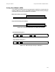
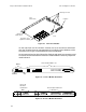
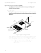
Figure 9-1. T1/E1 Voice Module
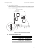
On the right front are 13 indicators. Of these, the six on the left are associated
with the voice/fax channels represented by the six Digital Voice Modules, while
the seven on the right are associated with the Voice Module.
Atthecenterandontherightsidearefourfeed-throughstackingconnectorsused
toconnecttheVoiceModuletothebaseunitmodulebelowitandtoanyexpansion
module above it.
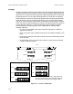
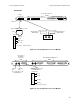
Figure 9-2. T1 Voice Module Rear Panel
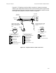
Figure 9-3. E1 Voice Module Rear Panel
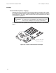
Rear
(Back Panel)
Front
Module
Switch Group
Receptacles (6) for
Digital Voice Modules
Stacking Connectors
Indicators
Test
DSX-1
Interface
Reserved for future use
Line 1 E1
Interface
Connectors
Reserved for future use