Getting Started with the Contivity Extranet Switch 2500 Part No.
Accuracy Notice The products and specifications, configurations, and other technical information regarding the products contained in this document are subject to change without notice. All statements, technical information, and recommendations contained in this document are believed to be accurate and reliable but are presented without warranty of any kind, expressed or implied, and users take full responsibility for their application of any products specified in this document.
Contents Preface Conventions .....................................................................................................................viii Documentation ..........................................................................................................viii Text ............................................................................................................................. ix User Interface ......................................................................................
Understanding the LEDs ..............................................................................................2-12 Chapter 3 Assigning a System Identity Startup Configuration Requirements ..............................................................................3-2 Management IP Address ..........................................................................................3-2 Subnet Mask ...........................................................................................................
Administrator ..........................................................................................................4-13 Date and Time ........................................................................................................4-13 Automatic Backup .........................................................................................................4-14 Chapter 5 Extranet Access Client Installation Windows 95 ................................................................................
Preface This guide steps you through the necessary tasks to get your Nortel NetworksTM Contivity Extranet Switch 2500TM up and running. Topics include: • Introducing the Contivity Extranet Switch • Assigning a System Identity • Managing the Switch • Installing the Extranet Access Client • Rack Mounting • Changing Hardware Configurations Complete details for configuring and monitoring the Switch are in Managing the Contivity Extranet Switch.
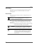
Preface Conventions This guide refers to the Contivity Extranet Switch as the CES or the Switch. This guide assumes that you are familiar with Web browsers and their general operation. Documentation This document uses the following conventions to distinguish among notes of varying importance: Note: Take notice. Notes contain helpful suggestions or references to materials contained in this document. TIP: Good idea.
Getting Started with the Convtivity Extranet Switch 2500 Text This guide uses the following text conventions: italic text Indicates new terms and book titles. screen text Indicates system output, for example, prompts and system messages. Example: Set Nortel Networks Trap Monitor Filters arrow ( → ) Shows menu paths. Example: Services → Available identifies the Switch services that are available.
Preface Related Publications The following table lists the associated documentation that you will need to configure and manage your Switch and describes the document’s objectives. x Document Description Contivity Extranet Switch Release Notes Provides the latest information, including known problems, workarounds, and special considerations. Managing the Contivity Extranet Switch (included on the CD) Provides complete details to configure, monitor, and troubleshoot your Switch.
Getting Started with the Convtivity Extranet Switch 2500 Nortel Networks Technical Publications You can print Nortel Networks technical manuals and release notes free, directly from the Internet. Go to support.baynetworks.com/library/tpubs/. Find the Nortel Networks product for which you need documentation. Then locate the specific category and model or version for your hardware or software product.
Preface Nortel Networks Customer Service If you purchased a service contract for your Nortel Networks product from a distributor or authorized reseller, contact the technical support staff for that distributor or reseller for assistance.
Chapter 1 Introducing the Contivity Extranet Switch The Switch The Nortel Networks Contivity Extranet Switch 2500 provides scalable, secure, manageable extranet access for up to 500 simultaneous users across the Public Data Network (PDN). The Switch's features include the most popular tunneling protocols, IP Security (IPsec), Point-to-Point Tunneling Protocol (PPTP), Layer 2 Forwarding Tunneling Protocol (L2TP), and Layer 2 Forwarding (L2F).
Getting Started with the Contivity Extranet Switch 2500 LAN Cable or D SL E-M ail S erver ISP PO P Contivity Extranet Switch NT Server Rem ote Em ployee Firewall IS P PO P P artner ISP P O P 56K M odem ISP PO P Router Authentication Server ISDN Reseller Internet Intranet Extranet Figure 1-1.
Introducing the Contivity Extranet Switch To restrict access, the Switch uses packet filtering based on Protocol ID, Direction, Source and Destination IP addresses, Source and Destination Ports, and TCP connection establishment. The unique quality of service (QoS) mechanisms include call admission and packet forwarding priorities, and support for Resource ReSerVation Protocol (RSVP).
Getting Started with the Contivity Extranet Switch 2500 Components List The following table lists all of the components and accessories of the Contivity Extranet Switch 2500. If for any reason you have not received all of the materials listed, contact Nortel Networks Customer Service.
Chapter 2 Cabling the Switch This chapter provides the following information: • Connecting power • LAN/WAN connections to: - 10/100BASE-TX LAN Interface - Dual V.35 interface - Single V.35 interface - T1 CSU/DSU interface - Hardware Accelerator • Serial interface connection • Understanding the LEDs This chapter describes the cables that you must use with the Switch, including pinouts for both LAN and WAN connections.
Getting Started with the Contivity Extranet Switch 2500 Connecting the Cables 1. Connect the power cords to the back of the Switch and to the electrical outlet. 2. Connect the 10/100BASE-TX LAN RJ-45 connector to the Switch. 3. Additionally, if you have LAN or WAN cards in Slots 1 through 3, connect those cables (refer to “Installing Option Cards” on page 7-4). NOTE: Slot 4 is not supported. Figure 2-1 shows the back view of the Switch.
Cabling the Switch Power Cord Requirements WARNING: 1. Do not modify or use the AC power cord(s) if it is not the exact type that is required for your power outlet. 2. Connect the LAN/WAN and serial port cables before you plug the Switch's power cord into the outlet. CAUTION: You should protect your Switch by plugging it into a surge suppressor.
Getting Started with the Contivity Extranet Switch 2500 LAN Interface Connections At least one LAN interface connection is for Web management. 100BASE-TX connections require Category 5, twisted-pair wire. The 100BASE-TX specification supports 100 Mb/s transmission over two pairs of Category 5 twisted-pair Ethernet wiring; one pair each for transmit and receive operations.
Cabling the Switch Dual V.35 WAN Interface (Optional) The Dual V.35 WAN connectors are located on a PCI card that offers two separate DB26S connectors that provide the signals needed to interface to V.35 equipment. Included in the accessory box are two cables that map the DB26S signals to a standard V.35 connector. Figure 2-3 shows the Dual V.35 interface. Figure 2-3. Dual V.35 Interface Table 2-1 shows the cable pinouts. Table 2-1. DB26S-to-V.35 Cable Pinouts DB26 Signal V.
Getting Started with the Contivity Extranet Switch 2500 20 DTR H 24 ETA U Note that you will need a DSU/CSU (digital service unit/channel service unit) between the WAN connection and the Switch.
Cabling the Switch Single V.35 WAN Interface (Optional) The Single V.35 WAN connector is located on a PCI card that offers a separate DB26S connector that provides the signals needed to interface to V.35 equipment. Included in the accessory box is a cable that maps the DB26S signals to a standard V.35 connector. Table 2-2 shows the cable pinouts. Table 2-2. DB26S-to-V.35 Cable Pinouts DB26 Signal V.
Getting Started with the Contivity Extranet Switch 2500 26 M0<-SIGNAL GROUND B 27 M1<-SIGNAL GROUND B 28 M2 no conn The following notes apply to the Single V.35 WAN Interface: 2-8 • You will need a DSU/CSU (digital service unit/channel service unit) between the WAN connection and the Switch. • At each end, Cable shield and connector shell must connect respectively to pin A of 34-pin connector and pin 1 of the standard 28-pin connector.
Cabling the Switch T1 CSU/DSU WAN Interface (Optional) The T1 CSU/DSU WAN crossover cable crosses the blue pair with the orange pair. This is different from the commonly available crossover cable, which crosses the green pair with the orange pair. No cables are supplied with the T1 CSU/DSU. Table 2-3 shows the cable pinouts. Table 2-3.
Getting Started with the Contivity Extranet Switch 2500 Hardware Accelerator/Encryption Card The Nortel Networkls Hardware Accelerator Encryption card is an encryption, compression, and authentication processor card with a PCI interface. It provides high-speed processing of the compute-intensive algorithms supported by today’s standard communications protocols. The card has a PCI revision 2.1 compliant interface, and contains on-board memory to store context information for all three engines.
Cabling the Switch Serial Interface Cable (Optional) Nortel Networks ships a serial cable with the Switch. Optionally, you can provide the Switch with a Management IP Address, subnet mask, and default gateway address among other things via the Serial Interface (refer to page 3-2 for details). Nortel Networks, however, recommends that you use the IP Address Configuration Utility diskette for easy initial IP address configuration (refer to page 3-3 for details).
Getting Started with the Contivity Extranet Switch 2500 Understanding the LEDs The Power LED is green when the power is on; if it is flashing, there is a hardware failure and you should contact Nortel Networks. The Hard Disk LED is green, and when it flashes the Switch is either reading or writing to the disk. The LAN Port LED is green, and when it flashes the Switch is either transmitting or receiving data.
Cabling the Switch LE D 4, R ed LED 3, G reen LED 2, Blue LED 1, Yellow Figure 2-5. Table 2-6. Single V.35 LEDs Single V.35 LED Indicators LED Description LED1 Power is on to the adapter and the onboard microcode is loaded. LED2 The signals CDC and DSR are on between the DSU and the adapter. LED2 detects receive link status. LED3 Cable is detected. LED4 No external transmit clock source is available. Figure 2-6 shows the T1 CSU/DSU LEDs.
Getting Started with the Contivity Extranet Switch 2500 LE D 4, R ed LED 2, Blue LED 1, Yellow LED 3, G reen Figure 2-6. Table 2-7. 2-14 T1 CSU/DSU LEDs T1 CSU/DSU LED Indicators LED Description LED1, Yellow Yellow alarm LED is lit when the far-end equipment is in the red alarm condition. LED2, Blue Blue alarm LED is lit when receiving an upstream failure denoted by an alarm indication signal (AIS). LED3, Green Normal operation.
Cabling the Switch Figure 2-7 shows the PCI card 10/100BASE-TX public LAN LEDs. Look at the condition of the LEDs, then examine the corresponding LED table to better understand the indications. Link LED LNK ACT Activity LED 100 TX 100Mb/s LED DATA Figure 2-7. Table 2-8. 10/100BASE-TX LAN LEDs 10/100BASE-TX LAN LED Card Indicators LED Indicator Description ACT/ LNK On or Flashing The card is sending or receiving network data. The frequency of the flashes increases with increased traffic.
Chapter 3 Assigning a System Identity This section describes how to assign a Management IP address, subnet mask, and optional default gateway address to your Switch. The Management IP address is used for all system services, such as HTTP, FTP, and SNMP. The Management IP address enables you to manage the Switch from a Web browser. Table 3-1 describes the choices you have when first configuring the required Switch parameters.
Getting Started with the Contivity Extranet Switch 2500 Startup Configuration Requirements This section describes the fields that you must complete with either the IP Address Configuration Utility or the serial interface configuration menu procedure. Management IP Address Enter a Management IP address for the system. You need this address to manage all system services, such as HTTP, FTP, and SNMP. This address must be accessible from one of the Switch's private physical interfaces.
Assigning a System Identity IP Address Configuration Utility Use this utility for the initial Switch configuration.
Getting Started with the Contivity Extranet Switch 2500 The following display appears while the program searches for an unconfigured Switch. Figure 3-1. 3. The program automatically enters the Serial Number for the first available Switch into the table of Contivity Switches. Figure 3-2.
Assigning a System Identity 4. Assign a Management IP Address and Subnet Mask to the Switch; the Default Gateway address is optional and can be added later (refer to “Startup Configuration Requirements” on page 3-2 for descriptions of the required fields). If you have more than one Switch, click Search to automatically add the additional Switch serial numbers. To verify the switches that have been discovered, you can refer to the serial number on the bar code on the bottom of the Switch. 5.
Getting Started with the Contivity Extranet Switch 2500 Serial Interface Configuration Note: Use the IP Address Configuration Utility (refer to page 3-3) to configure the Switch with its initial IP address. Alternatively, you can use the serial interface configuration menu to access the Switch via the serial interface of your PC.
Assigning a System Identity Procedure 1. Connect the serial cable from the Switch’s serial cable port to a PC communications port. Turn on the Switch. It can take the system approximately 3 minutes to start up. 2. Using a terminal emulation program, such as Hyper Terminal, press Enter and then supply a user name and password.
Getting Started with the Contivity Extranet Switch 2500 A sample display follows: Main Menu: 1) Interfaces 2) Administrator 3) Private Default Route Gateway* 10.0.0.10 4) Public Default Route Gateway* 5) Create A User Management Tunnel (IPsec) 6) Restricted Management Mode 7) Allow HTTP Management TRUE 8) Check Point Firewall Options 9) Shutdown P) Configure Serial Port C) Controlled Crash R) Reset System to Factory Defaults E) Exit, Save and Invoke Changes * Type 0.0.0.0 to delete.
Chapter 4 Managing the Switch This chapter describes the recommended Web browsers and the default login and passwords you need to access the Switch and the Quick Start Configuration. Recommended Web Browser Versions and Settings Nortel Networks Extranet Manager uses Java, JavaScript, and HTML features. For the management interface to function properly, verify that your Web browser meets the following minimum requirements. Platforms Supported Windows 95, Windows 98, Windows NT, and Macintosh®.
Getting Started with the Contivity Extranet Switch 2500 Preparing for Configuration To properly prepare for Installation and Configuration of the Contivity Extranet Switch, you should have the following items available: 4-2 • A Management IP Address for the system. You need this address to manage all system services, such as HTTP, FTP, and SNMP. • An IP Address for the LAN port that is available on the system board. • Any number of Public IP Addresses; e.g.
Managing the Switch Extranet Switch Welcome Display The Welcome display allows you to enter any of the configuration areas for the Contivity Extranet Switch, including: • Quick Start • Guided Config • Manage Switch • Manage from Notebook Before entering the configuration options, you should first register to activate licenses, warranties, and services. Table 4-1 shows the alternatives you have when first configuring your Switch.
Getting Started with the Contivity Extranet Switch 2500 Figure 4-1.
Managing the Switch Quick Start Click to begin the Quick Start configuration. This option allows you to configure interfaces, set up PPTP tunnels for up to three users, and establish a connection to the Switch. If you prepare for the configuration (refer to “Preparing for Configuration” on page 4-2), the Quick Start can take as little as 15 minutes to complete. Guided Config Click to begin the Guided Configuration. This option allows access to all Configuration Management facilities.
Getting Started with the Contivity Extranet Switch 2500 Register Online Click to register the Switch with Nortel Networks. It will only take a few minutes and it will give you access to the latest software and technical tips. Your Switch requires Internet access in order to register. Logging in and Supplying a Password Start up a Web browser and enter your Switch's Management IP Address. Select an option in the navigational menu and submenu, and then you are prompted for the Login and Password.
Managing the Switch Quick Start Configuration Prerequisites This display acts as a checklist for you to prepare for the Quick Start configuration. Assembling the information beforehand, and verifying that you can establish a PPTP Client session, makes Quick Start easy. Figure 4-2.
Getting Started with the Contivity Extranet Switch 2500 Required Environment This section describes the environment you need for the Quick Start configuration. If this does not describe your environment, use the Guided Configuration. Point-to-Point Tunnel Protocol (PPTP) tunnel access method PPTP is a tunneling protocol supported by Nortel Networks, Microsoft, and other vendors. The PPTP client is available for Windows 95 on the Nortel Networks CD and comes with Windows 98 and Windows NT 4.0 and later.
Managing the Switch Prerequisites • • IP configuration information (refer to “Preparing for Configuration” on page 4-2 for additional information): - Management IP Address for the Switch - Subnet Mask for the local subnet User IDs and Passwords: - PPTP Users (up to three) - Administrator Postconfiguration Testing • A PPTP remote user dialing in from an external system.
Getting Started with the Contivity Extranet Switch 2500 Configuration This display allows you to add a LAN port IP Address and Subnet Mask, establish the tunnel as Private (your private LAN) or Public (public data networks), and configure up to three PPTP Users and an Administrator with User IDs and Passwords. Additionally, you can set the system’s Date and Time. The following figures show partial displays of the Quick Start Configuration screen. Figure 4-3.
Managing the Switch LAN/WAN Interfaces Interfaces Lists the Management IP Address, LAN/WAN port, and any LAN or WAN cards. IP Address Enter an IP address for each interface on the Switch, including the LAN port. These IP addresses are used for tunnel creation. The IP Address consists of 32 bits, which are written as four octets in dotted-decimal format. For example: 192.168.34.
Getting Started with the Contivity Extranet Switch 2500 A host can send only enough packets to a Public interface to establish a tunnel connection. If the tunnel is not established before the preset maximum-number-of-packets-allowed counter is reached, then the packets from that host are discarded. Private Indicates that this interface is attached to the Private network and it can accept nontunneled networking protocols such as TCP/IP, FTP, HTTP, etc.
Managing the Switch Administrator The Administrator Settings allow you to change the Primary Administrator User ID (UID) and Password. The Primary Administrator User ID and Password combination always has access to all displays and controls. This UID is also used to access the serial port and the recovery disk. This Administrator's Password is also the Primary Administrator's Password. This password guarantees access to the Switch via the serial port or a Web browser.
Getting Started with the Contivity Extranet Switch 2500 Time Zone Select the appropriate time zone. Time zones can be a critical factor in the usage of digital certificates. Automatic Backup The Automatic Backup display under the Manage configuration option allows you to configure regular intervals when your system files are saved to designated host backup file servers. You should configure Automatic Backups immediately so that you will not lose system or configuration information in case of problems.
Chapter 5 Extranet Access Client Installation Windows 95 To install the Nortel Networks Extranet Access Client onto a Windows 95 PC, copy and load the four files that are on the Nortel Networks Extranet CD in the Client folder onto your hard drive. International software users must go to the Microsoft web site (http://support.microsoft.com/support) to get the MSDUN13 patch. 1. First, install Msdun13.exe (Microsoft Dial-up Networking update) by double-clicking on the file name.
Getting Started with the Contivity Extranet Switch 2500 5-2 a. Under the box titled, “The following network components are installed,” verify that the Client for Microsoft Networks is listed. If it is not, click on ADD, then select CLIENT, then click ADD again. Select Microsoft followed by Client for Microsoft Networks and finally click on the OK button. You will need your Windows 95 CD if it is not already copied onto your system. b.
Extranet Access Client Installation Windows 98 and Windows NT 4.0 To install the Nortel Networks Extranet Access Client onto a Windows 98 PC or Windows NT 4.0 workstation, you must copy the Extranet Access Client (Eac_25d.exe) that is on the Contivity Extranet Switch CD in the Client folder onto your hard drive. 1. Install Eac_25d.exe by double-clicking on the program name. The installation is self-explanatory. When prompted at the end of the installation, reboot your system. 2.
Chapter 6 Rack Mounting This chapter describes two systems you can use to mount your Switch into a chassis rack: • Rack-mount brackets for use with a two-post rack (refer to page 6-3). • Sliding rails for use with a four-post rack (optional purchase). Following are standard rack-mounting considerations that Nortel Networks recommends you follow: • The maximum recommended ambient temperature is 40 degrees Centigrade.
Getting Started with the Contivity Extranet Switch 2500 Mounting Brackets The following illustration shows mounting brackets being attached to a Switch in preparation of a two-post rack-mount installation. Position the brackets with the rack-mount bracket facing outward (as shown below). Optionally, you can mount the brackets in the rear of a rack. M ounting R ail O ptional R ear M ounting B racket R ack M ounting S crew s Front M ounting B racket Figure 6-1.
Rack Mounting Rack Mount Installation Procedure Nortel Networks recommends that you have two people available when installing the unit into the rack. 1. Position the bracket onto the Switch (as shown in Figure 6-1), then screw in the four rack-mounting screws. Repeat this step on the other side of the chassis. 2. With one person holding the Switch in place, insert the two front screws on each side to secure the Switch and brackets into the rack.
Getting Started with the Contivity Extranet Switch 2500 R ack M ounting S crew s Slide Locking Bracket R ack M ounting B racket(s) M ounting R ail Figure 6-2.
Rack Mounting Sliding Rail Installation Procedure NOTES • Insert all bracket mounting screws so that the screw heads are inside the slides. • Do not use washers on the inside of the slides. • Mount the side brackets parallel to each other. • Determine if the unit will slide to the front or rear of the rack. These instructions are for sliding the chassis forward; reverse the closed-end bracket for rearward travel. 1.
Chapter 7 Changing Hardware Configurations This chapter describes how to change existing hardware configurations, including installing LAN or WAN cards and adding memory. NOTE: Wear an antistatic band when handling electronic components for the Switch to avoid damaging them. Warning: Turn off the Switch and unplug it before installing LAN or WAN cards or system memory. To install LAN and WAN cards you must first remove the Switch’s top cover.
Getting Started with the Contivity Extranet Switch 2500 Removing the Top Cover The following illustration shows you how to remove the top cover from the Switch. You must remove the cover to: • Install LAN or WAN cards. • Install additional memory. 1 R em ove the three screw s from the top of the cover 2 Lift rear of cover up, and pull aw ay from unit. Figure 7-1. 7-2 Removing the Top Cover 1. Turn off the Switch’s power and unplug it. 2. Remove the three screws at the top rear of the chassis.
Changing Hardware Configurations System Board Figure 7-2 shows the Switch's system board, in particular the DIMMs, option cards slots, and the cooling fan. F acto ry Insta lled D IM M s (1 , 2 , o r 4 ) 43 2 1 CPU C oo ling F a n 1 2 3 4 4 O p tio n C ard S lots (on ly th re e a re usa ble ) Figure 7-2. Switch's System Board Warning: Beware of danger if the battery is incorrectly replaced. Replace with the same or an equivalent battery only, as recommended by the manufacturer.
Getting Started with the Contivity Extranet Switch 2500 Installing Option Cards The following illustration shows you how install LAN or WAN option cards into the Switch. You can use Slots 1 to 3 for any mix of LAN and WAN cards. Note that Slot 4 is not supported. R e a r o f U n it F ille r P a n e l O p tio n C a rd M o th e rb o a rd O p tio n C a rd S lo ts Figure 7-3. 7-4 Installing LAN or WAN Cards 1. Power off the Switch and remove the power cord. 2. Remove the top cover. 3.
Changing Hardware Configurations Installing Additional DIMMs The following illustration shows you how to unlock a Dual Inline Memory Module (DIMM), and remove or install a DIMM. Install the DIMM in the next available slot (i.e., if the DIMM # 1 slot is populated, then add the next DIMM to the DIMM # 2 slot). Alignment Keys 1 4 3 2 Locking Lever Figure 7-4.
Getting Started with the Contivity Extranet Switch 2500 Follow these steps to install a DIMM. 1. Turn off the Switch. 2. Remove the power cord. 3. Remove the top cover. 4. Press down the locking levers on both sides of the DIMM. 5. Pull the DIMM up to remove it from the slot. 6. Place a new DIMM in the slot, making sure to properly position the DIMM's alignment keys. Make sure the DIMM is pressed firmly into the socket. 7.
Changing Hardware Configurations Removing the Front Bezel The following illustration shows you how to remove the front bezel from the Switch. Note that you do not need to turn off the Switch to remove the front bezel. You must remove the bezel to insert the Recovery Diskette. S lide fingers behind front bezel and firm ly pull forw ard in the direction of arrows. F ront B ezel Figure 7-5. Front Bezel Removal Note that the first few times you remove the front bezel it might seem to resist removal.
Getting Started with the Contivity Extranet Switch 2500 Remove the Switch front bezel as follows: 7-8 1. Optionally, remove the three screws at the top rear of the chassis, then slide the top cover back. 2. Slide your fingers between the front bezel and the Switch. 3. Pull forward firmly.
Appendix A Specifications Physical Length: 23.75 in. (60.33 cm) Width: 16.75 in. (42.55 cm) Height: 7.00 in. (17.78 cm) Weight: 51.0 lbs (112.2 kg) Electrical: 110-120/220-240V, 6.
Appendix B Special Notices This appendix provides information on statements of conditions, the Nortel Networks Software License Agreement, and RADIUS attribution. Statement of Conditions In the interest of improving internal design, operational function, and/or reliability, Nortel Networks, Inc. reserves the right to make changes to the products described in this document without notice. Nortel Networks, Inc.
Getting Started with the Contivity Extranet Switch 2500 Federal Communications Commission (FCC) Compliance Notice: Radio Frequency Notice Note: This equipment has been tested and found to comply with the limits for a Class A digital device, pursuant to Part 15 of the FCC rules. These limits are designed to provide reasonable protection against harmful interference when the equipment is operated in a commercial environment. This equipment generates, uses, and can radiate radio frequency energy.
Special Notices Canadian Department of Communications Radio Interference Regulations This digital apparatus, the Contivity Extranet Switch 2500, does not exceed the Class A limits for radio-noise emissions from digital apparatus as set out in the Radio Interference Regulations of the Canadian Department of Communications.
Getting Started with the Contivity Extranet Switch 2500 2. Restrictions on use; reservation of rights. The Software and user manuals are protected under copyright laws. Nortel Networks and/or its licensors retain all title and ownership in both the Software and user manuals, including any revisions made by Nortel Networks or its licensors. The copyright notice must be reproduced and included with any copy of any portion of the Software or user manuals.
Special Notices 4. Limitation of liability. IN NO EVENT WILL Nortel NETWORKS OR ITS LICENSORS BE LIABLE FOR ANY COST OF SUBSTITUTE PROCUREMENT; SPECIAL, INDIRECT, INCIDENTAL, OR CONSEQUENTIAL DAMAGES; OR ANY DAMAGES RESULTING FROM INACCURATE OR LOST DATA OR LOSS OF USE OR PROFITS ARISING OUT OF OR IN CONNECTION WITH THE PERFORMANCE OF THE SOFTWARE, EVEN IF Nortel NETWORKS HAS BEEN ADVISED OF THE POSSIBILITY OF SUCH DAMAGES.
Getting Started with the Contivity Extranet Switch 2500 9. General. If any provision of this Agreement is held to be invalid or unenforceable by a court of competent jurisdiction, the remainder of the provisions of this Agreement shall remain in full force and effect. This Agreement will be governed by the laws of the state of California. Should you have any questions concerning this Agreement, contact Nortel Networks, Inc., 4401 Great America Parkway, P.O. Box 58185, Santa Clara, California 95054-8185.
Special Notices THIS SOFTWARE IS PROVIDED "AS IS" WITHOUT WARRANTY OF ANY KIND, EITHER EXPRESS OR IMPLIED, INCLUDING WITHOUT LIMITATION WARRANTIES OF MERCHANTABILITY AND FITNESS FOR A PARTICULAR PURPOSE. THE REGENTS OF THE UNIVERSITY OF MICHIGAN AND MERIT NETWORK, INC. DO NOT WARRANT THAT THE FUNCTIONS CONTAINED IN THE SOFTWARE WILL MEET LICENSEE'S REQUIREMENTS OR THAT OPERATION WILL BE UNINTERRUPTED OR ERROR FREE. The Regents of the University of Michigan and Merit Network, Inc.
Index Numerics default gateway 3-2, 4-11 DHCP 4-8 100BASE-TX interface 2-4 10BASE-T interface 2-4 A additional memory installing 7-2 administrator 4-9 administrator settings 4-13 DIMMs 7-3 installing 7-5 diskette IP Address Configuration Utility 3-3 documentation map x DSU/CSU required 2-6, 2-8 E electrical A-1 antistatic 7-1 automatic backup 4-14 F C front bezel removing 7-7, 7-8 Category 3, 4 wiring requirements 2-4 Category 5 wiring requirements 2-4 caution viii configuration choices 4-3 G gat
L R LAN cards 4-11 installing 7-2, 7-4 rack mount 6-2 LDAP 4-8 recovery diskette drive 7-7 LEDs system board 2-12 registration 4-3, 4-5 length A-1 RJ-45 pinouts 2-4 login default 4-6 relative humidity A-1 S M Manage Extranet Switch 4-3, 4-5 safety 7-1 power off 7-4, 7-6 memory size 7-6 serial cable connectors 2-11 Microsoft Internet Explorer 4-1 serial interface configuration requirements 3-6 connector 2-11 N Nortel Networks Contivity Extranet Switch Administrator’s Guide 4-3 sliding rail
temperature A-1 terminal emulation communication requirements 3-6 serial interface 3-7 testing a configuration 4-9 text conventions ix time 4-13 top cover removing 7-2 U user ID 4-12 user interface ix W WAN cards 4-11 installing 7-2, 7-4 WAN connection DSU/CSU 2-6, 2-8 warning viii Web browsers 3-5, 4-1 weight A-1 Welcome display 4-3 width A-1 Index-3