
User's Manual


150 Chapter 12 Installing Analog Terminal Adapters
P0609324 01
Note: The termination on the analog interface may consist of any combination of devices subject
only to the requirement that the sum of the RENs of all the devices does not exceed the REN of the
interface the device is connect to.
Analog transmission parameters (North American systems, only)
Input impedance at tip and ring 600 ohms
Return loss > 20 dB for 200 to 3,400 Hz (when Network terminated
with 600 ohms)
Insertion loss on an internal call ATA 2 to Business Communications Manager system loss
3.0 dB ± 0.5 dB
Insertion loss on an external call ATA 2 to Business Communications Manager system loss
2.2 dB ± 1.0 dB
Business Communications Manager system to ATA 2 loss
0.5 dB ± 1.0 dB
To test insertion loss once the analog device is attached to the system, refer to “Testing
insertion loss measurement” on page 154.
Data device transmission requirements using an ATA 2
The ATA 2 is compatible with all commercial FAX and modem protocols. When connected to
an ATA 2, the Business Communications Manager system supports data transmission rates a
maximum of and including 28.8 kbit/s.
CAUTION: Nortel Networks cannot guarantee the maximum data transmission rate because
the maximum rate is subject to the quality of the end-to-end channel.
analog loop resistance less than 200 ohms (for example: 730 m of 0.4 mm wire or
2,400 ft. of 26 AWG wire.)
external line to ATA 2 must follow the transmission network requirements
described in the data communication device specifications
transmission rates (baud) over 1,200 bps require a modulation design compatible
with the telephone line bandwidth. Use a conditioned
external line to prevent data corruption during transmission
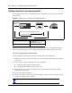
Note: Maximum loss from the ATA 2 analog terminal to the
CO must be 10 dB or less at 1 kHz. If the loss exceeds this
limit, condition the line. This loss ensures correct data
transmission for different types of data terminals.