
Survivable Remote Gateway Configuration Guide

Chapter 4 CS 1000 considerations 43
SRG50 Configuration Guide
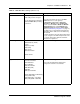
To configure Emergency Services Access
1 Verify that a remote access package has been assigned to the VoIP trunks (see Remote Access
Package for VoIP trunks on page 76).
2 Obtain the ESA Special Number (SPN).
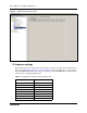
3 In Element Manager, access the Dialing Plan - Routing panel (Configuration > Telephony >
Dialing Plan > Routing) and click the Destination Codes tab.
4 Add a destination code corresponding to the ESA SPN for the SRG branch office.
5 In the Destination Codes table, click the Absorbed Length field of the ESA SPN destination
code. The numbers indicate the number of digits the SRG absorbs, from left to right.
6 Select the number of digits to absorb so that just the Emergency Services DN (ESDN)
remains.
7 In the Destination Codes table, click the Normal Route field of the ESA SPN destination
code. Enter a public route to the PSTN trunks.
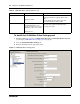
8 Navigate to the Dialing Plan - Public Network panel (Configuration > Dialing Plan > Public
Network).
9 In the Public Network DN Lengths subpanel, verify that there is a DN Prefix of 911 with a
DN Length of 3.
If not, add the 911 DN Prefix. If required, double click the DN Length field and then change
the value to 3.
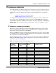
To configure on-site notification
To use the on-site notification for Emergency Services, you need to include a LAN CTE port
in your keycode.
In
Note: The Normal Route field defaults to 000. Route 000 (click the
Routes tab) is preconfigured to Use Pool A and cannot be changed. Pool
A is preconfigured for PSTN trunks in the default state. Hence, if the
default state of Pool A has not been changed, leave the Normal Route
field as 000.
To check the state of Pool A, navigate to Configuration > Lines >
Active Physical Lines. Pool A must be assigned to at least one Trunk
Type that provides access to the PSTN.
Do not configure Alternate Routes.