
Network Device Maintenance and Diagnostics

June 2007 Replacing basic chassis components
1005r Server Maintenance and Diagnostics 119
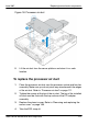
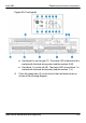
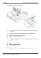
Figure 23: Cooling fan assembly
6 Loosen the captive screw (B) that attaches the four-fan assembly to
the chassis.
7 Lift the fan module straight up and remove it from the chassis.
8 Lower the new fan module into place.
9 Tighten the captive screw (B).
10 Connect the fan cables to the correct fan connectors on the front
panel I/O board. The fan connectors are labeled on the front panel I/
O board.
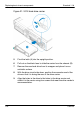
11 Replace the processor air duct.
12 Replace the chassis cover.
13 Take the ESD strap off.
14 Connect the AC power cords, peripheral devices, and restart the
server.