
User manual
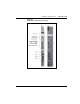
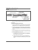
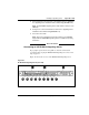
Table Of Contents
- Title page
- New in this release
- List of Procedures
- How to get help
- Finding the latest updates on the Nortel web site
- System information
- Introduction
- Preparing for installation
- Placing the fourth module on a column
- Positioning and leveling equipment
- Installing AC power
- Installing overhead cable tray kits
- Installing DC power
- Contents
- DC-powered systems
- Candeo DC power systems
- Large Candeo modules
- Small Candeo modules
- Installation reference guide
- Configuration reference guide
- Safety ground/protective earth and logic return wiring
- Cabling and connecting the grounding leads
- Connecting the power plant frame ground (or safety ground) leads
- Four-Feed PDU
- Installing the Four-Feed PDU
- Installing safety ground/protective earth wiring
- Connecting power from the power plant to the PDU
- Connecting UK power to the Four-Feed PDU
- System monitor connections
- Planning and designating a Main Distribution Frame
- Installing Power Failure Transfer Units
- Configuring the system monitor
- Connecting a system terminal or modem
- Contents
- About the system terminal
- Connecting a terminal
- Connecting a terminal to a COM port
- Connecting a switch box and terminal to COM1 and COM2 ports
- Connecting a switch box and terminal to SDI and COM1 ports
- Connecting a modem
- Configuring a modem
- Connecting a modem to an SDI port
- Connecting a modem to switch box, COM2 ports, SDI ports
- Cabling Common Equipment in a Single Group system
- Contents
- Cabling guidelines
- Core/Net module
- Cabling the Core side
- Cabling the I/O panel
- Cabling the Network side
- Configuring and cabling the Clock Controllers
- Network Group 0: Shelf 0 to Shelf 1
- Connecting the 3PE faceplates in the Core/Net modules
- Inspecting CNI to 3PE factory installed cables
- Connecting the Core/Net backplanes
- Optioning the System Utility Card
- Connecting Core modules to a LAN
- Cabling Common Equipment in a Multi Group system
- Contents
- Cabling guidelines
- Core/Net module
- Cabling the Core/Net module backplane
- Disconnecting cables from the Core/Net module backplane
- Optioning the System Utility Card
- Core shelf cabling
- Installing the CP PIV to I/O panel cables
- Connecting the Core module to a LAN
- Cabling a Dual Ring Fiber Network
- FIJI card cabling
- Installing the Shelf 0 fiber optic ring (ascending)
- Installing the Shelf 1 fiber optic ring (descending)
- FIJI to FIJI cabling
- Connecting the Clock Controller cables
- Cabling network modules and loops
- Contents
- Network-to-network cabling
- Network module connections
- Network Group 0: Shelf 0 to Shelf 1
- Connecting the 3PE faceplates in the Core/Net modules
- Connecting the Core/Net backplanes
- Connecting Groups 1 through 7: Shelf 0 to Shelf 1
- Connecting the Network modules to the Core/Net modules
- Connecting the 3PE cables to the 3PE fanout panels
- Cabling a Superloop Network Card - single column
- Cabling a Superloop Network Card - multiple columns
- Cabling lines and trunks
- Powering up the system and initial loading
- Performing acceptance tests
- Installing earthquake bracing
- Adding a module to a column
- Installing a Signaling Server
- Contents
- Introduction
- Readiness checklist
- Installing the CP PM Signaling Server hardware
- Connections
- Installing the Signaling Server software
- First boot of a new Nortel CP PM Signaling Server
- Unpacking Help files for Virtual Terminal Emulator
- Logging in to the Signaling Server
- Verifying a successful configuration
- Testing the Leader Signaling Server
- Index

Page 396 of 458 Installing a Signaling Server
NN43021-310 Standard 02.02 October 2008
— Insert the end of a longer RJ-45 CAT5 Ethernet cable (not
supplied) into the ELAN network interface port (ELAN port) on
the faceplate of the server
— Insert the other end of the RJ-45 CAT5 Ethernet cable into an
Ethernet port on the ELAN Ethernet switch
2 Connect the Signaling Server to the TLAN subnet.
• if the Call Server is not connected to the Media Gateway Controller
(MGC)
— Insert the end of one of the 25-cm RJ-45 CAT5 Ethernet cables
shipped with the server (NTDU0606E6) into the TLAN network
interface port (TLAN port) on the faceplate of the server
— Insert the other end of the 25-cm RJ-45 CAT5 Ethernet cable
into the MGC TLAN Ethernet port
• if the Call Server is connected to the MGC
— Insert the end of a longer RJ-45 CAT5 Ethernet cable (not
supplied) into the TLAN network interface port (TLAN port) on
the faceplate of the server
— Insert the other end of the RJ-45 CAT5 Ethernet cable into an
Ethernet port on the TLAN Ethernet switch
End of Procedure
Note: If the Call Server is connected to the Media Gateway Controller,
you can not use the 25-cm CAT5 Ethernet cables shipped with the
Signaling Server (NTDU0606E6). You must obtain CAT5 Ethernet
cables that are long enough to connect the Signaling Server directly to the
ELAN and TLAN Ethernet switches from the faceplate ELAN and
TLAN Ethernet ports.
Complete Procedure 75 to connect a Nortel CP PM Signaling Server (model
NTDW66AAE5) to the ELAN and TLAN subnets of a CS 1000M system.
IMPORTANT!
Connecting a Nortel CP PM Signaling Server to the ELAN and TLAN
subnets of a CS 1000M system causes a service disruption.