
User manual
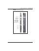
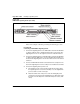
Table Of Contents
- Title page
- New in this release
- List of Procedures
- How to get help
- Finding the latest updates on the Nortel web site
- System information
- Introduction
- Preparing for installation
- Placing the fourth module on a column
- Positioning and leveling equipment
- Installing AC power
- Installing overhead cable tray kits
- Installing DC power
- Contents
- DC-powered systems
- Candeo DC power systems
- Large Candeo modules
- Small Candeo modules
- Installation reference guide
- Configuration reference guide
- Safety ground/protective earth and logic return wiring
- Cabling and connecting the grounding leads
- Connecting the power plant frame ground (or safety ground) leads
- Four-Feed PDU
- Installing the Four-Feed PDU
- Installing safety ground/protective earth wiring
- Connecting power from the power plant to the PDU
- Connecting UK power to the Four-Feed PDU
- System monitor connections
- Planning and designating a Main Distribution Frame
- Installing Power Failure Transfer Units
- Configuring the system monitor
- Connecting a system terminal or modem
- Contents
- About the system terminal
- Connecting a terminal
- Connecting a terminal to a COM port
- Connecting a switch box and terminal to COM1 and COM2 ports
- Connecting a switch box and terminal to SDI and COM1 ports
- Connecting a modem
- Configuring a modem
- Connecting a modem to an SDI port
- Connecting a modem to switch box, COM2 ports, SDI ports
- Cabling Common Equipment in a Single Group system
- Contents
- Cabling guidelines
- Core/Net module
- Cabling the Core side
- Cabling the I/O panel
- Cabling the Network side
- Configuring and cabling the Clock Controllers
- Network Group 0: Shelf 0 to Shelf 1
- Connecting the 3PE faceplates in the Core/Net modules
- Inspecting CNI to 3PE factory installed cables
- Connecting the Core/Net backplanes
- Optioning the System Utility Card
- Connecting Core modules to a LAN
- Cabling Common Equipment in a Multi Group system
- Contents
- Cabling guidelines
- Core/Net module
- Cabling the Core/Net module backplane
- Disconnecting cables from the Core/Net module backplane
- Optioning the System Utility Card
- Core shelf cabling
- Installing the CP PIV to I/O panel cables
- Connecting the Core module to a LAN
- Cabling a Dual Ring Fiber Network
- FIJI card cabling
- Installing the Shelf 0 fiber optic ring (ascending)
- Installing the Shelf 1 fiber optic ring (descending)
- FIJI to FIJI cabling
- Connecting the Clock Controller cables
- Cabling network modules and loops
- Contents
- Network-to-network cabling
- Network module connections
- Network Group 0: Shelf 0 to Shelf 1
- Connecting the 3PE faceplates in the Core/Net modules
- Connecting the Core/Net backplanes
- Connecting Groups 1 through 7: Shelf 0 to Shelf 1
- Connecting the Network modules to the Core/Net modules
- Connecting the 3PE cables to the 3PE fanout panels
- Cabling a Superloop Network Card - single column
- Cabling a Superloop Network Card - multiple columns
- Cabling lines and trunks
- Powering up the system and initial loading
- Performing acceptance tests
- Installing earthquake bracing
- Adding a module to a column
- Installing a Signaling Server
- Contents
- Introduction
- Readiness checklist
- Installing the CP PM Signaling Server hardware
- Connections
- Installing the Signaling Server software
- First boot of a new Nortel CP PM Signaling Server
- Unpacking Help files for Virtual Terminal Emulator
- Logging in to the Signaling Server
- Verifying a successful configuration
- Testing the Leader Signaling Server
- Index

Installing a Signaling Server Page 395 of 458
Communication Server 1000M and Meridian 1 Large System Installation and Commissioning
5 Set the COM port on the maintenance terminal as follows:
• Terminal type: VT100
• Speed: 9 600
• Data bits: 8
• Parity: none
• Stop bits: 1
• Flow control: none
Note: The CP PM Signaling Server is shipped with the Admin Serial port
set to 9600 Bit/s. Other available speeds are 19 200, 38 400, and 115 200
Bits. You can change the port speed using the maintenance terminal. To
verify or change the baud rate on a Nortel CP PM Signaling Server, see
Signaling Server: Installation and Commissioning (NN43001-312).
6 Configure the Signaling Server maintenance terminal. Refer to Signaling
Server: Installation and Commissioning (NN43001-312).
End of Procedure
Complete Procedure 74 to connect a Nortel CP PM Signaling Server (model
NTDW61BAE5) to the ELAN and TLAN subnets of a CS 1000E system.
Procedure 74
Connecting a CP PM Signaling Server to the ELAN and TLAN subnets of
a CS 1000E system
1 Connect the Signaling Server to the ELAN subnet.
• if the Call Server is not connected to the Media Gateway Controller
(MGC) CE port
— Insert the end of one of the 25-cm RJ-45 CAT5 Ethernet cables
shipped with the server (NTDU0606E6) into the ELAN network
interface port (ELAN port) on the faceplate of the server
— insert the other end of the 25-cm RJ-45 CAT5 Ethernet cable
into the MGC ELAN Ethernet port
• if the Call Server is connected to the CE port