
User manual
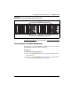
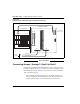
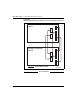
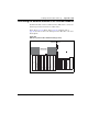
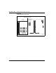
Table Of Contents
- Title page
- New in this release
- List of Procedures
- How to get help
- Finding the latest updates on the Nortel web site
- System information
- Introduction
- Preparing for installation
- Placing the fourth module on a column
- Positioning and leveling equipment
- Installing AC power
- Installing overhead cable tray kits
- Installing DC power
- Contents
- DC-powered systems
- Candeo DC power systems
- Large Candeo modules
- Small Candeo modules
- Installation reference guide
- Configuration reference guide
- Safety ground/protective earth and logic return wiring
- Cabling and connecting the grounding leads
- Connecting the power plant frame ground (or safety ground) leads
- Four-Feed PDU
- Installing the Four-Feed PDU
- Installing safety ground/protective earth wiring
- Connecting power from the power plant to the PDU
- Connecting UK power to the Four-Feed PDU
- System monitor connections
- Planning and designating a Main Distribution Frame
- Installing Power Failure Transfer Units
- Configuring the system monitor
- Connecting a system terminal or modem
- Contents
- About the system terminal
- Connecting a terminal
- Connecting a terminal to a COM port
- Connecting a switch box and terminal to COM1 and COM2 ports
- Connecting a switch box and terminal to SDI and COM1 ports
- Connecting a modem
- Configuring a modem
- Connecting a modem to an SDI port
- Connecting a modem to switch box, COM2 ports, SDI ports
- Cabling Common Equipment in a Single Group system
- Contents
- Cabling guidelines
- Core/Net module
- Cabling the Core side
- Cabling the I/O panel
- Cabling the Network side
- Configuring and cabling the Clock Controllers
- Network Group 0: Shelf 0 to Shelf 1
- Connecting the 3PE faceplates in the Core/Net modules
- Inspecting CNI to 3PE factory installed cables
- Connecting the Core/Net backplanes
- Optioning the System Utility Card
- Connecting Core modules to a LAN
- Cabling Common Equipment in a Multi Group system
- Contents
- Cabling guidelines
- Core/Net module
- Cabling the Core/Net module backplane
- Disconnecting cables from the Core/Net module backplane
- Optioning the System Utility Card
- Core shelf cabling
- Installing the CP PIV to I/O panel cables
- Connecting the Core module to a LAN
- Cabling a Dual Ring Fiber Network
- FIJI card cabling
- Installing the Shelf 0 fiber optic ring (ascending)
- Installing the Shelf 1 fiber optic ring (descending)
- FIJI to FIJI cabling
- Connecting the Clock Controller cables
- Cabling network modules and loops
- Contents
- Network-to-network cabling
- Network module connections
- Network Group 0: Shelf 0 to Shelf 1
- Connecting the 3PE faceplates in the Core/Net modules
- Connecting the Core/Net backplanes
- Connecting Groups 1 through 7: Shelf 0 to Shelf 1
- Connecting the Network modules to the Core/Net modules
- Connecting the 3PE cables to the 3PE fanout panels
- Cabling a Superloop Network Card - single column
- Cabling a Superloop Network Card - multiple columns
- Cabling lines and trunks
- Powering up the system and initial loading
- Performing acceptance tests
- Installing earthquake bracing
- Adding a module to a column
- Installing a Signaling Server
- Contents
- Introduction
- Readiness checklist
- Installing the CP PM Signaling Server hardware
- Connections
- Installing the Signaling Server software
- First boot of a new Nortel CP PM Signaling Server
- Unpacking Help files for Virtual Terminal Emulator
- Logging in to the Signaling Server
- Verifying a successful configuration
- Testing the Leader Signaling Server
- Index

Page 241 of 458
Communication Server 1000M and Meridian 1 Large System Installation and Commissioning
262
Cabling network modules and loops
Contents
This section contains information on the following topics:
Network-to-network cabling . . . . . . . . . . . . . . . . . . . . . . . . . . . . . . . . . 241
Network module connections . . . . . . . . . . . . . . . . . . . . . . . . . . . . . . . . 242
Network Group 0: Shelf 0 to Shelf 1. . . . . . . . . . . . . . . . . . . . . . . . . . . 242
Connecting the 3PE faceplates in the Core/Net modules . . . . . . . . . . . 242
Connecting the Core/Net backplanes . . . . . . . . . . . . . . . . . . . . . . . . . . 243
Connecting Groups 1 through 7: Shelf 0 to Shelf 1 . . . . . . . . . . . . . . . 244
Connecting the Network modules to the Core/Net modules. . . . . . . . . 247
Connecting the 3PE cables to the 3PE fanout panels . . . . . . . . . . . . . . 252
Cabling a Superloop Network Card – single column . . . . . . . . . . . . . . 254
Cabling a Superloop Network Card – multiple columns . . . . . . . . . . . 258
Network-to-network cabling
Cabling between NT8D35 Network Modules interconnects the two
half-groups to build a full-network group. The first full-group is located in the
Core/Network module together with the CPU. The maximum length of the
interconnecting cables between the two modules is 0.6 m (2 ft). The two
half-group network modules must therefore be stacked on top of one another.
The cables are then routed from the backplane of one module to the backplane
of the other through the vertical holes in the rear horizontal cable trough of
the modules.