
User manual
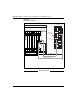


Table Of Contents
- Title page
- New in this release
- List of Procedures
- How to get help
- Finding the latest updates on the Nortel web site
- System information
- Introduction
- Preparing for installation
- Placing the fourth module on a column
- Positioning and leveling equipment
- Installing AC power
- Installing overhead cable tray kits
- Installing DC power
- Contents
- DC-powered systems
- Candeo DC power systems
- Large Candeo modules
- Small Candeo modules
- Installation reference guide
- Configuration reference guide
- Safety ground/protective earth and logic return wiring
- Cabling and connecting the grounding leads
- Connecting the power plant frame ground (or safety ground) leads
- Four-Feed PDU
- Installing the Four-Feed PDU
- Installing safety ground/protective earth wiring
- Connecting power from the power plant to the PDU
- Connecting UK power to the Four-Feed PDU
- System monitor connections
- Planning and designating a Main Distribution Frame
- Installing Power Failure Transfer Units
- Configuring the system monitor
- Connecting a system terminal or modem
- Contents
- About the system terminal
- Connecting a terminal
- Connecting a terminal to a COM port
- Connecting a switch box and terminal to COM1 and COM2 ports
- Connecting a switch box and terminal to SDI and COM1 ports
- Connecting a modem
- Configuring a modem
- Connecting a modem to an SDI port
- Connecting a modem to switch box, COM2 ports, SDI ports
- Cabling Common Equipment in a Single Group system
- Contents
- Cabling guidelines
- Core/Net module
- Cabling the Core side
- Cabling the I/O panel
- Cabling the Network side
- Configuring and cabling the Clock Controllers
- Network Group 0: Shelf 0 to Shelf 1
- Connecting the 3PE faceplates in the Core/Net modules
- Inspecting CNI to 3PE factory installed cables
- Connecting the Core/Net backplanes
- Optioning the System Utility Card
- Connecting Core modules to a LAN
- Cabling Common Equipment in a Multi Group system
- Contents
- Cabling guidelines
- Core/Net module
- Cabling the Core/Net module backplane
- Disconnecting cables from the Core/Net module backplane
- Optioning the System Utility Card
- Core shelf cabling
- Installing the CP PIV to I/O panel cables
- Connecting the Core module to a LAN
- Cabling a Dual Ring Fiber Network
- FIJI card cabling
- Installing the Shelf 0 fiber optic ring (ascending)
- Installing the Shelf 1 fiber optic ring (descending)
- FIJI to FIJI cabling
- Connecting the Clock Controller cables
- Cabling network modules and loops
- Contents
- Network-to-network cabling
- Network module connections
- Network Group 0: Shelf 0 to Shelf 1
- Connecting the 3PE faceplates in the Core/Net modules
- Connecting the Core/Net backplanes
- Connecting Groups 1 through 7: Shelf 0 to Shelf 1
- Connecting the Network modules to the Core/Net modules
- Connecting the 3PE cables to the 3PE fanout panels
- Cabling a Superloop Network Card - single column
- Cabling a Superloop Network Card - multiple columns
- Cabling lines and trunks
- Powering up the system and initial loading
- Performing acceptance tests
- Installing earthquake bracing
- Adding a module to a column
- Installing a Signaling Server
- Contents
- Introduction
- Readiness checklist
- Installing the CP PM Signaling Server hardware
- Connections
- Installing the Signaling Server software
- First boot of a new Nortel CP PM Signaling Server
- Unpacking Help files for Virtual Terminal Emulator
- Logging in to the Signaling Server
- Verifying a successful configuration
- Testing the Leader Signaling Server
- Index

Cabling Common Equipment in a Multi Group system Page 221 of 458
Communication Server 1000M and Meridian 1 Large System Installation and Commissioning
Figure 92 on page 222 displays the COM and LAN cable connections.
Procedure 32
Installing the CP PIV to I/O panel cables
1 Connect COM1 on the CP PIV faceplate to J25 on the I/O panel with
cable NT4N88AA.
2 Connect COM2 on the CP PIV faceplate to J21 on the back of the I/O
panel with cable NT4N88BA.
3 Connect the Dual Ethernet Adapter (RJ-45) for I/O Panel (NTRE40AA) to
J31. Secure the adapter to J31 with the two screws included in the
shipment.
4 Connect LAN 1 (Ethernet) on the CP PIV faceplate to J31 (top) of the I/O
panel with cable NT4N90BA.
This connection can only be made after the Dual Ethernet Adapter is
installed (see step 3 above).
Note: If a LAN switch is not used, connect LAN 1 in Core 0 to LAN 1 in
Core 1.
5 Connect a crossover Ethernet cable (NTRC17BA) from the LAN 2 port in
Core 0 to the LAN 2 port Core 1. This connection is for Core redundancy.
Note: To ensure EMI shielding, route the cable along the front of the card
cage and through the sides of the Core/Net modules.
6 Repeat steps 1 through 4 in the second Core/Net module.
CAUTION
Damage to Equipment
Label all cables on both ends before installation.
Labels help ensure that the cables are properly
routed and connected. Cable labels also help
installers to troubleshoot problems and replace
equipment.