
User manual
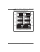

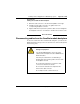


Table Of Contents
- Title page
- New in this release
- List of Procedures
- How to get help
- Finding the latest updates on the Nortel web site
- System information
- Introduction
- Preparing for installation
- Placing the fourth module on a column
- Positioning and leveling equipment
- Installing AC power
- Installing overhead cable tray kits
- Installing DC power
- Contents
- DC-powered systems
- Candeo DC power systems
- Large Candeo modules
- Small Candeo modules
- Installation reference guide
- Configuration reference guide
- Safety ground/protective earth and logic return wiring
- Cabling and connecting the grounding leads
- Connecting the power plant frame ground (or safety ground) leads
- Four-Feed PDU
- Installing the Four-Feed PDU
- Installing safety ground/protective earth wiring
- Connecting power from the power plant to the PDU
- Connecting UK power to the Four-Feed PDU
- System monitor connections
- Planning and designating a Main Distribution Frame
- Installing Power Failure Transfer Units
- Configuring the system monitor
- Connecting a system terminal or modem
- Contents
- About the system terminal
- Connecting a terminal
- Connecting a terminal to a COM port
- Connecting a switch box and terminal to COM1 and COM2 ports
- Connecting a switch box and terminal to SDI and COM1 ports
- Connecting a modem
- Configuring a modem
- Connecting a modem to an SDI port
- Connecting a modem to switch box, COM2 ports, SDI ports
- Cabling Common Equipment in a Single Group system
- Contents
- Cabling guidelines
- Core/Net module
- Cabling the Core side
- Cabling the I/O panel
- Cabling the Network side
- Configuring and cabling the Clock Controllers
- Network Group 0: Shelf 0 to Shelf 1
- Connecting the 3PE faceplates in the Core/Net modules
- Inspecting CNI to 3PE factory installed cables
- Connecting the Core/Net backplanes
- Optioning the System Utility Card
- Connecting Core modules to a LAN
- Cabling Common Equipment in a Multi Group system
- Contents
- Cabling guidelines
- Core/Net module
- Cabling the Core/Net module backplane
- Disconnecting cables from the Core/Net module backplane
- Optioning the System Utility Card
- Core shelf cabling
- Installing the CP PIV to I/O panel cables
- Connecting the Core module to a LAN
- Cabling a Dual Ring Fiber Network
- FIJI card cabling
- Installing the Shelf 0 fiber optic ring (ascending)
- Installing the Shelf 1 fiber optic ring (descending)
- FIJI to FIJI cabling
- Connecting the Clock Controller cables
- Cabling network modules and loops
- Contents
- Network-to-network cabling
- Network module connections
- Network Group 0: Shelf 0 to Shelf 1
- Connecting the 3PE faceplates in the Core/Net modules
- Connecting the Core/Net backplanes
- Connecting Groups 1 through 7: Shelf 0 to Shelf 1
- Connecting the Network modules to the Core/Net modules
- Connecting the 3PE cables to the 3PE fanout panels
- Cabling a Superloop Network Card - single column
- Cabling a Superloop Network Card - multiple columns
- Cabling lines and trunks
- Powering up the system and initial loading
- Performing acceptance tests
- Installing earthquake bracing
- Adding a module to a column
- Installing a Signaling Server
- Contents
- Introduction
- Readiness checklist
- Installing the CP PM Signaling Server hardware
- Connections
- Installing the Signaling Server software
- First boot of a new Nortel CP PM Signaling Server
- Unpacking Help files for Virtual Terminal Emulator
- Logging in to the Signaling Server
- Verifying a successful configuration
- Testing the Leader Signaling Server
- Index

Page 212 of 458 Cabling Common Equipment in a Multi Group system
NN43021-310 Standard 02.02 October 2008
Checking Core card (front side) installation
All Core cards are factory installed. The Core cards (front side) are:
1 NT4N65 cPCI Core Network Interface (cCNI) cards. Each system
contains between one and four NT4N65 cCNI cards per Core/Net
Module. The cCNI cards are located in slots c9-c12. If not already
installed, install a P0605337 cPCI Card Slot Filler Panel to cover any of
slots, c10 - c12, which do not contain cCNIs.
Note: In the NT4N41 Core/Net module, port 0 on the NT4N65 Core to
Network Interface (cCNI) Card in slot c9 must be configured as
“Group 0.” Communication between the bv cCNI and 3PE cards for
Group 0 is accomplished through the NT4N29 cable.
Note: Slots c13 and c14 are left empty. If not already installed, install a
P0605337 cPCI Card Slot Filler Panel in each slot.
2 NT4N48 System Utility (Sys Util) card. The System Utility card is
located in slot c15.
3 NT4N39AA Call Processor PIV (CP PIV). This card is located in the
slot marked CP.
Cabling the Core/Net module backplane
Before you connect cables to the backplane, visually inspect the backplane
shroud connectors to make sure there are no bent pins.
CAUTION
Damage to Equipment
Pins may be bent or broken if you try to insert the
cable connector at an angle. Do not push the
connector in any further after you hear the click.