
User manual
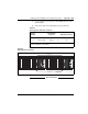
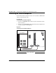


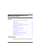


Table Of Contents
- Title page
- New in this release
- List of Procedures
- How to get help
- Finding the latest updates on the Nortel web site
- System information
- Introduction
- Preparing for installation
- Placing the fourth module on a column
- Positioning and leveling equipment
- Installing AC power
- Installing overhead cable tray kits
- Installing DC power
- Contents
- DC-powered systems
- Candeo DC power systems
- Large Candeo modules
- Small Candeo modules
- Installation reference guide
- Configuration reference guide
- Safety ground/protective earth and logic return wiring
- Cabling and connecting the grounding leads
- Connecting the power plant frame ground (or safety ground) leads
- Four-Feed PDU
- Installing the Four-Feed PDU
- Installing safety ground/protective earth wiring
- Connecting power from the power plant to the PDU
- Connecting UK power to the Four-Feed PDU
- System monitor connections
- Planning and designating a Main Distribution Frame
- Installing Power Failure Transfer Units
- Configuring the system monitor
- Connecting a system terminal or modem
- Contents
- About the system terminal
- Connecting a terminal
- Connecting a terminal to a COM port
- Connecting a switch box and terminal to COM1 and COM2 ports
- Connecting a switch box and terminal to SDI and COM1 ports
- Connecting a modem
- Configuring a modem
- Connecting a modem to an SDI port
- Connecting a modem to switch box, COM2 ports, SDI ports
- Cabling Common Equipment in a Single Group system
- Contents
- Cabling guidelines
- Core/Net module
- Cabling the Core side
- Cabling the I/O panel
- Cabling the Network side
- Configuring and cabling the Clock Controllers
- Network Group 0: Shelf 0 to Shelf 1
- Connecting the 3PE faceplates in the Core/Net modules
- Inspecting CNI to 3PE factory installed cables
- Connecting the Core/Net backplanes
- Optioning the System Utility Card
- Connecting Core modules to a LAN
- Cabling Common Equipment in a Multi Group system
- Contents
- Cabling guidelines
- Core/Net module
- Cabling the Core/Net module backplane
- Disconnecting cables from the Core/Net module backplane
- Optioning the System Utility Card
- Core shelf cabling
- Installing the CP PIV to I/O panel cables
- Connecting the Core module to a LAN
- Cabling a Dual Ring Fiber Network
- FIJI card cabling
- Installing the Shelf 0 fiber optic ring (ascending)
- Installing the Shelf 1 fiber optic ring (descending)
- FIJI to FIJI cabling
- Connecting the Clock Controller cables
- Cabling network modules and loops
- Contents
- Network-to-network cabling
- Network module connections
- Network Group 0: Shelf 0 to Shelf 1
- Connecting the 3PE faceplates in the Core/Net modules
- Connecting the Core/Net backplanes
- Connecting Groups 1 through 7: Shelf 0 to Shelf 1
- Connecting the Network modules to the Core/Net modules
- Connecting the 3PE cables to the 3PE fanout panels
- Cabling a Superloop Network Card - single column
- Cabling a Superloop Network Card - multiple columns
- Cabling lines and trunks
- Powering up the system and initial loading
- Performing acceptance tests
- Installing earthquake bracing
- Adding a module to a column
- Installing a Signaling Server
- Contents
- Introduction
- Readiness checklist
- Installing the CP PM Signaling Server hardware
- Connections
- Installing the Signaling Server software
- First boot of a new Nortel CP PM Signaling Server
- Unpacking Help files for Virtual Terminal Emulator
- Logging in to the Signaling Server
- Verifying a successful configuration
- Testing the Leader Signaling Server
- Index
Cabling Common Equipment in a Single Group system Page 201 of 458
Communication Server 1000M and Meridian 1 Large System Installation and Commissioning
a. Use the extraction tool to disconnect the NT4N29 cables from the
Core backplane.
b. Connect the cables to the appropriate group (see Table 24).
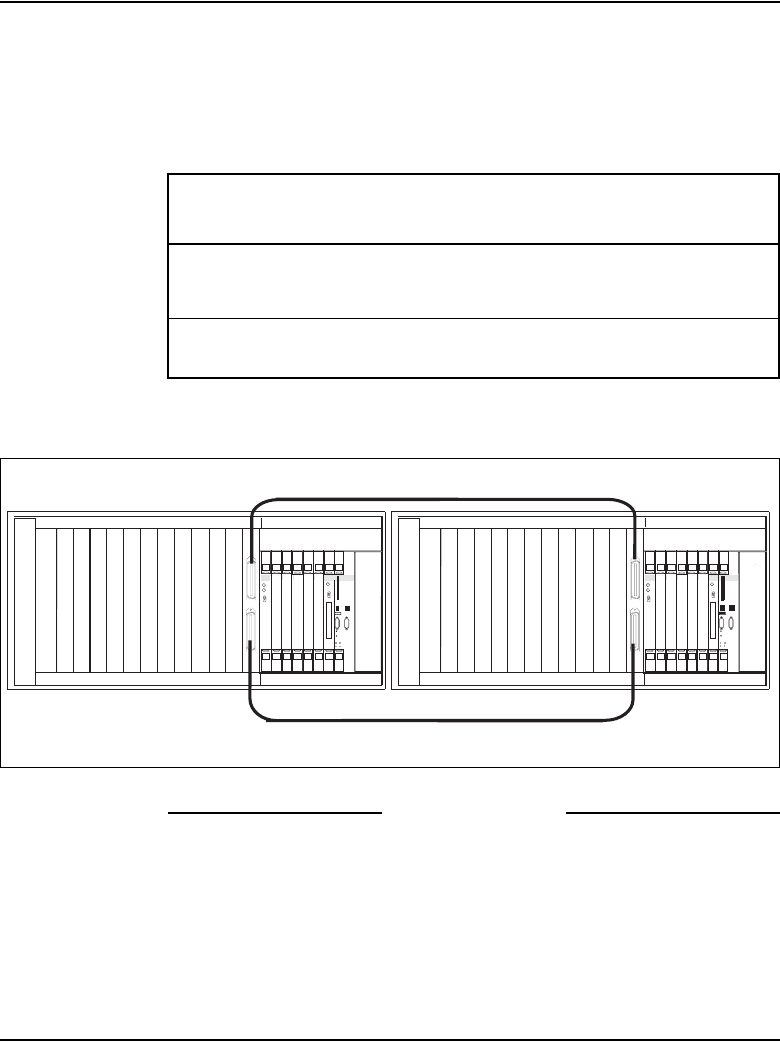
Figure 81
3PE faceplate connections
End of Procedure
Table 24
Fanout panel to 3PE card connectors
Group
Number
Fanout Panel
connector 3PE card connector
0
0
connects from
connects from
9-0, J3
9-0, J4
to
to
A
B
Note: Group 0 cables (NT4N29) connect the fanout panel directly to the
network backplane of Core/Net 1.
PS
Net
NT8D17 Conference/TDS Card
NT8D04 Superloop Network Card
NT8D04 Superloop Network Card
NT8D04 Superloop Network Card
QPC43R Peripheral Signaling Card
NTRB53 CIock Controller card
PS 0 1 2 3 4 5 6 7 8 9 10 11
SYS
UTIL
L
U
C
cCNI
A
B
Enb
Dis
L
C
Core
Enb
Dis
c9 c10 c11 c12 c13 c14 c15 CP
PS
Net
NT8D17 Conference/TDS Card
NT8D04 Superloop Network Card
NT8D04 Superloop Network Card
NT8D04 Superloop Network Card
QPC43R Peripheral Signaling Card
NTRB53 CIock Controller card
PS 0 1 2 3 4 5 6 7 8 9 10 11
SYS
UTIL
L
U
USB
C
INIT
RESET
cCNI
A
B
Enb
Dis
L
LAN 2
C
COM 1
CP
PIV
Core
Enb
Dis
c9 c10 c11 c12 c13 c14 c15 CP
NT8D80AZ cable
NT8D80AZ cable
553-9123_3pe_r26revised
LAN 1
COM 2
USB
INIT
RESET
LAN 2
COM 1
CP
PIV
LAN 1
COM 2