
User manual
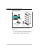
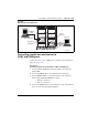
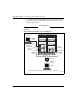
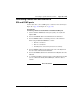
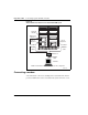
Table Of Contents
- Title page
- New in this release
- List of Procedures
- How to get help
- Finding the latest updates on the Nortel web site
- System information
- Introduction
- Preparing for installation
- Placing the fourth module on a column
- Positioning and leveling equipment
- Installing AC power
- Installing overhead cable tray kits
- Installing DC power
- Contents
- DC-powered systems
- Candeo DC power systems
- Large Candeo modules
- Small Candeo modules
- Installation reference guide
- Configuration reference guide
- Safety ground/protective earth and logic return wiring
- Cabling and connecting the grounding leads
- Connecting the power plant frame ground (or safety ground) leads
- Four-Feed PDU
- Installing the Four-Feed PDU
- Installing safety ground/protective earth wiring
- Connecting power from the power plant to the PDU
- Connecting UK power to the Four-Feed PDU
- System monitor connections
- Planning and designating a Main Distribution Frame
- Installing Power Failure Transfer Units
- Configuring the system monitor
- Connecting a system terminal or modem
- Contents
- About the system terminal
- Connecting a terminal
- Connecting a terminal to a COM port
- Connecting a switch box and terminal to COM1 and COM2 ports
- Connecting a switch box and terminal to SDI and COM1 ports
- Connecting a modem
- Configuring a modem
- Connecting a modem to an SDI port
- Connecting a modem to switch box, COM2 ports, SDI ports
- Cabling Common Equipment in a Single Group system
- Contents
- Cabling guidelines
- Core/Net module
- Cabling the Core side
- Cabling the I/O panel
- Cabling the Network side
- Configuring and cabling the Clock Controllers
- Network Group 0: Shelf 0 to Shelf 1
- Connecting the 3PE faceplates in the Core/Net modules
- Inspecting CNI to 3PE factory installed cables
- Connecting the Core/Net backplanes
- Optioning the System Utility Card
- Connecting Core modules to a LAN
- Cabling Common Equipment in a Multi Group system
- Contents
- Cabling guidelines
- Core/Net module
- Cabling the Core/Net module backplane
- Disconnecting cables from the Core/Net module backplane
- Optioning the System Utility Card
- Core shelf cabling
- Installing the CP PIV to I/O panel cables
- Connecting the Core module to a LAN
- Cabling a Dual Ring Fiber Network
- FIJI card cabling
- Installing the Shelf 0 fiber optic ring (ascending)
- Installing the Shelf 1 fiber optic ring (descending)
- FIJI to FIJI cabling
- Connecting the Clock Controller cables
- Cabling network modules and loops
- Contents
- Network-to-network cabling
- Network module connections
- Network Group 0: Shelf 0 to Shelf 1
- Connecting the 3PE faceplates in the Core/Net modules
- Connecting the Core/Net backplanes
- Connecting Groups 1 through 7: Shelf 0 to Shelf 1
- Connecting the Network modules to the Core/Net modules
- Connecting the 3PE cables to the 3PE fanout panels
- Cabling a Superloop Network Card - single column
- Cabling a Superloop Network Card - multiple columns
- Cabling lines and trunks
- Powering up the system and initial loading
- Performing acceptance tests
- Installing earthquake bracing
- Adding a module to a column
- Installing a Signaling Server
- Contents
- Introduction
- Readiness checklist
- Installing the CP PM Signaling Server hardware
- Connections
- Installing the Signaling Server software
- First boot of a new Nortel CP PM Signaling Server
- Unpacking Help files for Virtual Terminal Emulator
- Logging in to the Signaling Server
- Verifying a successful configuration
- Testing the Leader Signaling Server
- Index

Connecting a system terminal or modem Page 173 of 458
Communication Server 1000M and Meridian 1 Large System Installation and Commissioning
Connecting a terminal
During the system installation and for continuing system operation, a
terminal must be connected to an SDI port in a network slot to provide an
I/O interface to the active CPU in the system (for local access). In addition, a
data terminal equipment (DTE) port (COM1) and a data communication
equipment (DCE) port (COM2) on the Call Processor Pentium IV (CP PIV)
card can be used for direct access of the cPCI Core/Network Module.
Typically, the CP card ports (COM ports) or COM1 and COM2 are
pre-configured on I/O addresses four and five.
The COM1 and COM2 ports are active only when the CPU associated with
the CP card is active. Therefore, the COM1 and COM2 ports should not be
used as the only I/O connection for the system.
When the initial installation is complete, you must leave a terminal or a
modem connected to the system. One SDI port in a network slot must be
permanently connected to a terminal or modem. On the COM1 and COM2
ports you can:
1 disconnect the ports;
2 leave terminals connected for local monitoring; and,
3 connect modems for remote monitoring.
The ABCDE-Switch, which provides up to four-to-one switching, is
available from Nortel as part number A0377992. The switch box can be used
to connect the SDI and COM1 and COM2 ports to a terminal or a modem. If
used, one switch box must be used for terminals and one for modems.
Commercial terminal servers can also be used to concentrate the serial ports
on the equipment in a telecom room.
Terminal guidelines
During an installation, you can connect terminals to the COM1 ports for split
mode monitoring, or programming, or both. (Due to the speed of the system
messages displayed, personal computers are useful for file capture and
review.)