
User manual
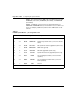
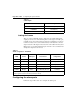

Table Of Contents
- Title page
- New in this release
- List of Procedures
- How to get help
- Finding the latest updates on the Nortel web site
- System information
- Introduction
- Preparing for installation
- Placing the fourth module on a column
- Positioning and leveling equipment
- Installing AC power
- Installing overhead cable tray kits
- Installing DC power
- Contents
- DC-powered systems
- Candeo DC power systems
- Large Candeo modules
- Small Candeo modules
- Installation reference guide
- Configuration reference guide
- Safety ground/protective earth and logic return wiring
- Cabling and connecting the grounding leads
- Connecting the power plant frame ground (or safety ground) leads
- Four-Feed PDU
- Installing the Four-Feed PDU
- Installing safety ground/protective earth wiring
- Connecting power from the power plant to the PDU
- Connecting UK power to the Four-Feed PDU
- System monitor connections
- Planning and designating a Main Distribution Frame
- Installing Power Failure Transfer Units
- Configuring the system monitor
- Connecting a system terminal or modem
- Contents
- About the system terminal
- Connecting a terminal
- Connecting a terminal to a COM port
- Connecting a switch box and terminal to COM1 and COM2 ports
- Connecting a switch box and terminal to SDI and COM1 ports
- Connecting a modem
- Configuring a modem
- Connecting a modem to an SDI port
- Connecting a modem to switch box, COM2 ports, SDI ports
- Cabling Common Equipment in a Single Group system
- Contents
- Cabling guidelines
- Core/Net module
- Cabling the Core side
- Cabling the I/O panel
- Cabling the Network side
- Configuring and cabling the Clock Controllers
- Network Group 0: Shelf 0 to Shelf 1
- Connecting the 3PE faceplates in the Core/Net modules
- Inspecting CNI to 3PE factory installed cables
- Connecting the Core/Net backplanes
- Optioning the System Utility Card
- Connecting Core modules to a LAN
- Cabling Common Equipment in a Multi Group system
- Contents
- Cabling guidelines
- Core/Net module
- Cabling the Core/Net module backplane
- Disconnecting cables from the Core/Net module backplane
- Optioning the System Utility Card
- Core shelf cabling
- Installing the CP PIV to I/O panel cables
- Connecting the Core module to a LAN
- Cabling a Dual Ring Fiber Network
- FIJI card cabling
- Installing the Shelf 0 fiber optic ring (ascending)
- Installing the Shelf 1 fiber optic ring (descending)
- FIJI to FIJI cabling
- Connecting the Clock Controller cables
- Cabling network modules and loops
- Contents
- Network-to-network cabling
- Network module connections
- Network Group 0: Shelf 0 to Shelf 1
- Connecting the 3PE faceplates in the Core/Net modules
- Connecting the Core/Net backplanes
- Connecting Groups 1 through 7: Shelf 0 to Shelf 1
- Connecting the Network modules to the Core/Net modules
- Connecting the 3PE cables to the 3PE fanout panels
- Cabling a Superloop Network Card - single column
- Cabling a Superloop Network Card - multiple columns
- Cabling lines and trunks
- Powering up the system and initial loading
- Performing acceptance tests
- Installing earthquake bracing
- Adding a module to a column
- Installing a Signaling Server
- Contents
- Introduction
- Readiness checklist
- Installing the CP PM Signaling Server hardware
- Connections
- Installing the Signaling Server software
- First boot of a new Nortel CP PM Signaling Server
- Unpacking Help files for Virtual Terminal Emulator
- Logging in to the Signaling Server
- Verifying a successful configuration
- Testing the Leader Signaling Server
- Index

Configuring the system monitor Page 169 of 458
Communication Server 1000M and Meridian 1 Large System Installation and Commissioning
Procedure 17
Configuring the alarm ports
1 Select “Alarm Severity and Output” from the System Manager display
screen.
2 Under “Alarm Name”, select the line with “AC Fail”, and change “Output
Port” to 1.
3 Under “Alarm Name”, select the line with “Major”, and change “Output
Port” to 2 (by default it should already be 2).
4 Under “Alarm Name”, select the line with “Low Float”, and change “Output
Port” to Port 3.
5 All other “Output Ports” should be set to “None”.
Note: For more detailed information refer to the Alarms section in the
Candeo Power System User Guide (P0914425).
End of Procedure
Customizing alarms
Under “Alarm Severity and Outputs”, the ports and severity can be
configured per customers requirements. If the customer wishes they can
utilize signals DCON1, DCON2 and DCON3 by connecting them to other
available “No Connect” ports (connect commons on J8 to the battery return
bus) and customize as desired.
Under the alarm output screen the relay state is defaulted to “not energized”
when alarm is on. To change the relay state an engineering password is
required. Contact Astec support for a temporary password to change this
field. After the setting has been changed use the normally open contacts when
wiring J8.
Note: For further information on all alarms that can be configured for
the Candeo, see the Alarms section in the Candeo Power Systems User
Guide (P0914425) and Candeo SP 48300 Power System AP6C55AA
User Manual (P7000154).