
User's Manual


Appendix B: I/O, maintenance, and extender cable description Page 869 of 910
IP Line Description, Installation and Maintenance
Procedure 125
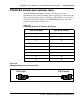
Removing an NT8D81BA cable
1 Identify the I/O panel and backplane designation that corresponds to the
LEFT slot of the pair of card slots, viewed from the front, in which the
ITG ISL Trunk card is installed.
2 Disconnect the filter from the I/O panel using a screwdriver and needle
nose pliers. Retain the fasteners.
3 Power down the IPE shelf.
4 Remove the IPE module I/O safety panel.
5 To remove the ribbon cables from the IPE backplane, apply gentle
pressure on the tab on the right side of the shroud while pulling on the
connector until it pulls free from the shroud.
Remove connector 1 first, then remove connectors 2 and 3.
6 Discard the NT8D81BA cable.
End of Procedure
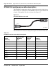
Install the NTCW84JA filter and NT8D81AA cable
Follow the steps in Procedure 126 to install the NTCW84JA filter and
NT8D81AA cable.
Procedure 126
Installing an NTCW84JA filter and NT8D81AA cable
1 Install the NTCW84JA special IPE filter connector in the vacant I/O panel
slot using retained hardware.
2 Install the NT8D81AA ribbon cable connectors in the IPE module
backplane shroud. Be sure to install the connector so the label is facing
right with the arrow pointing up and the connector is fully engaged into the
shroud:
a. Install connector 1, (labeled UP1^) into backplane shroud 1.
b. Install connector 2, (labeled UP2^) into backplane shroud 2.
c. Install connector 3, (labeled UP3^) into backplane shroud 3.