
User's Manual


Appendix B: I/O, maintenance, and extender cable description Page 867 of 910
IP Line Description, Installation and Maintenance
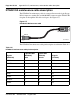
Figure 279 on page 868 shows the designations for the backplane end of the
cables, the backplane slot designations for the cable connections, and the
associated network segments for the backplane slots.
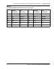
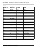
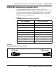
Table 116
NT8D37 cable connections
Backplane slots – shroud rows I/O panel/cable designation
L0–1, 2, 3
L1–1, 2, 3
L2–1, 2, 3
L3–1, 2, 3
L4–1, 2, 3
L5–1, 2, 3
L6–1, 2, 3
L7–1, 2, 3
L8–1, 2, 3
L9–1, 2, 3
L10–1, 2, 3
L11–1, 2, 3
L12–1, 2, 3
L13–1, 2, 3
L14–1, 2, 3
L15–1, 2, 3
A
B
C
D
E
F
G
H
K
L
M
N
R
S
T
U