
User's Manual


Page 336 of 910 Installation and initial configuration of an IP Telephony node
553-3001-365 Standard 4.00 August 2005
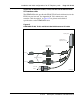
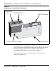
Procedure 19
Installing the Shielded 50-pin to Serial/ELAN/TLAN Adapter onto the
Media Card
1 Install the Shielded 50-pin to Serial/ELAN/TLAN Adapter into the card
connector (1, 2, 3, or 4) where the Media Card is located.
2 Connect a shielded Cat 5 cable from the customer’s TLAN switch
equipment to the port labeled “TLAN”.
3 Connect a shielded Category 5 cable from the customer’s ELAN hub or
switch equipment to the port labeled “ELAN”.
4 Install the NTAG81CA serial cable into the faceplate Maintenance port.
End of Procedure
Initial configuration of IP Line 4.5 data
Before beginning the configuration:
• Ensure the system is running CS 1000 Release 4.5 software.
• Verify the License system limit in LD 22. The License system limit must
have sufficient unused units to support the number of IP Phones to be
installed. For more information, refer to Software Input/Output:
Maintenance (553-3001-511).
• Expand the License limit, if necessary, by ordering additional Licenses.
See “Licenses” on page 64 for more information.
Summary of procedures
1 Configure IP address for the system active ELNK Ethernet network
interface (LD 117). See page 337.
2 Configure VoIP bandwidth management zones (LD 117). See page 338.
3 Configure physical TNs (LD 14). See page 342.
4 Configure virtual superloops for IP Phones. See page 347.
5 Configure IP Phone features in LD 11. See page 351.