
Ethernet Routing Switch Installation Guide
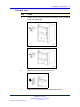
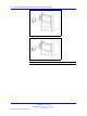
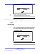

Table Of Contents
- toc
- Regulatory Information and Safety Precautions
- International Regulatory Statements of Conformity
- National Electromagnetic Compliance (EMC) Statements of Complian
- ICES Statement (Canada only)
- CE Marking Statement (Europe only)
- VCCI Statement (Japan/Nippon only)
- BSMI Statement for 8310, and 8306 Chassis (Taiwan only)
- MIC notice for 8310, and 8306 chassis (Republic of Korea only)
- National Safety Statements of Compliance
- NOM Statement 8310 and 8306 Chassis (Mexico only)
- Información NOM (unicamente para México)
- Denan Statement (Japan/Nippon only)
- Safety Messages
- Software license
- New in this release
- Introduction
- Chassis installation fundamentals
- Ethernet Routing Switch 8310 and 8306 chassis installation
- Switch operations
- Part Numbers
- Technical specifications
- Navigation
- Ethernet Routing Switch 8310 chassis specifications
- Ethernet Routing Switch 8306 chassis specifications
- Ethernet Routing Switch 8301 AC power supply specifications
- Ethernet Routing Switch 8302 AC power supply specifications
- Ethernet Routing Switch 8005DC power supply specifications
- Ethernet Routing Switch 8005DI DC power supply specifications
- Translations of safety messages
- Regulatory Information and Safety Precautions
44 Switch operations
ATTENTION
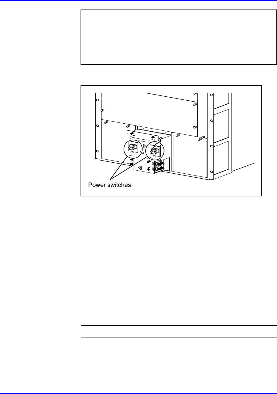
When you first install a chassis that contains two or three
power supplies, you must turn on two of the power supply units
simultaneously. If you wait longer to turn on the second power
supply, one of the power supplies could shut down. To correct this
condition, turn off both power supplies, wait at least 30 seconds, and
then turn on both power supplies again simultaneously.
For more information about the power switch locations, see the
following figure.
2 Verify that the power output LED for each power supply lights
green.
3 Verify that the power supply status LEDs and the fan LED on the
8393SF/CPU or 8394SF/CPU module light green.
After you turn on the switch, each module automatically
initiates a diagnostic test to verify proper module function. See
“Successful installation verification” (page 32).
4 Verify that air is flowing from the cooling fans out through the
vents of the chassis.
5 If the power supply LED remains off, or if you cannot feel air flow
from the chassis vents, turn the DC power supplies off, and then
turn them on again.
6 If the problem persists, contact the Nortel Technical Solutions
Center.
--End--
Powering on AC power supplies
Power on the AC power supplies to provide power to the switch.
Nortel Ethernet Routing Switch 8300
Installation — Chassis
NN46200-309 01.01 Standard
16 June 2008
Copyright © 2008 Nortel Networks
.