
Ethernet Routing Switch Installation Guide
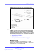
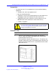
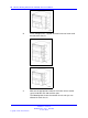
Table Of Contents
- toc
- Regulatory Information and Safety Precautions
- International Regulatory Statements of Conformity
- National Electromagnetic Compliance (EMC) Statements of Complian
- ICES Statement (Canada only)
- CE Marking Statement (Europe only)
- VCCI Statement (Japan/Nippon only)
- BSMI Statement for 8310, and 8306 Chassis (Taiwan only)
- MIC notice for 8310, and 8306 chassis (Republic of Korea only)
- National Safety Statements of Compliance
- NOM Statement 8310 and 8306 Chassis (Mexico only)
- Información NOM (unicamente para México)
- Denan Statement (Japan/Nippon only)
- Safety Messages
- Software license
- New in this release
- Introduction
- Chassis installation fundamentals
- Ethernet Routing Switch 8310 and 8306 chassis installation
- Switch operations
- Part Numbers
- Technical specifications
- Navigation
- Ethernet Routing Switch 8310 chassis specifications
- Ethernet Routing Switch 8306 chassis specifications
- Ethernet Routing Switch 8301 AC power supply specifications
- Ethernet Routing Switch 8302 AC power supply specifications
- Ethernet Routing Switch 8005DC power supply specifications
- Ethernet Routing Switch 8005DI DC power supply specifications
- Translations of safety messages
- Regulatory Information and Safety Precautions
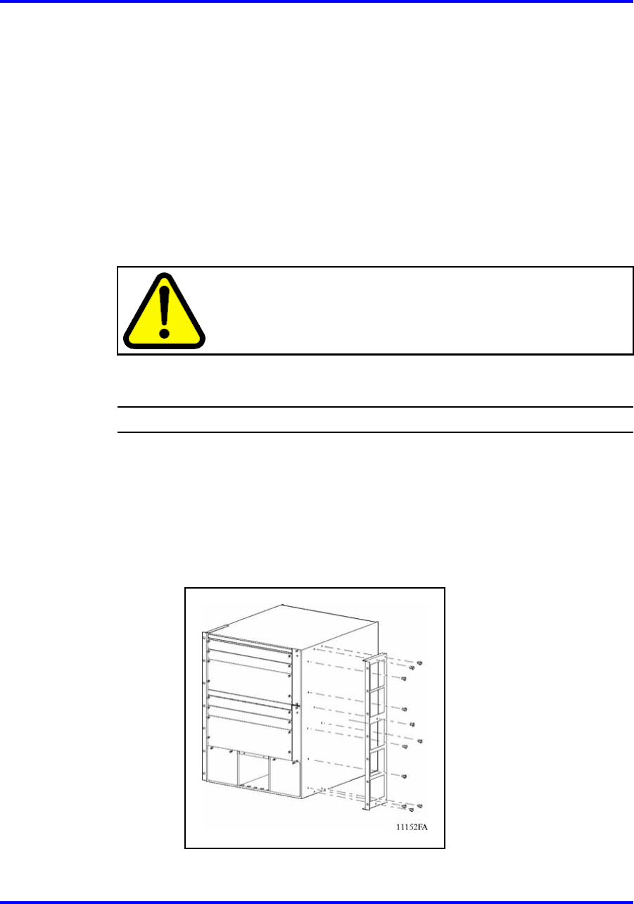
Mounting the Ethernet Routing Switch 8310 and 8306 chassis in an equipment rack 37
Prerequisites
• To mount the chassis in an equipment rack, you need the following
equipment:
—
standard 19 in. (48.2 cm) equipment rack
—
two rack mounting brackets
—
14 Machine screws for the mounting brackets on the 8306 chassis
(22 Machine screws for the brackets on the 8310 chassis)
—
10 WAFER head screws and washers for the 8306 chassis (14
WAFER head screws and washers for the 8310 chassis)
—
a Phillips screwdriver
CAUTION
See “Procedure job aid: Maximum number of chassis installed
in 7-foot rack” (page 40) for the maximum number of chassis
that you can install in a 7-foot rack.
Procedure steps
Step Action
1 Hold each rack-mounting bracket against one side of the
chassis. Make sure that the attachment holes in the bracket
match the holes in the chassis.
Each bracket fits only one side of the chassis. The brackets are
labeled R (right) and L (left). If the mounting holes do not line up
between a bracket and the chassis, try that bracket on the other
side of the chassis.
Nortel Ethernet Routing Switch 8300
Installation — Chassis
NN46200-309 01.01 Standard
16 June 2008
Copyright © 2008 Nortel Networks
.