
Ethernet Routing Switch Installation Guide
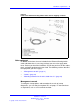
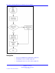
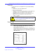
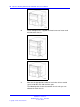
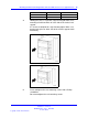
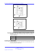
Table Of Contents
- toc
- Regulatory Information and Safety Precautions
- International Regulatory Statements of Conformity
- National Electromagnetic Compliance (EMC) Statements of Complian
- ICES Statement (Canada only)
- CE Marking Statement (Europe only)
- VCCI Statement (Japan/Nippon only)
- BSMI Statement for 8310, and 8306 Chassis (Taiwan only)
- MIC notice for 8310, and 8306 chassis (Republic of Korea only)
- National Safety Statements of Compliance
- NOM Statement 8310 and 8306 Chassis (Mexico only)
- Información NOM (unicamente para México)
- Denan Statement (Japan/Nippon only)
- Safety Messages
- Software license
- New in this release
- Introduction
- Chassis installation fundamentals
- Ethernet Routing Switch 8310 and 8306 chassis installation
- Switch operations
- Part Numbers
- Technical specifications
- Navigation
- Ethernet Routing Switch 8310 chassis specifications
- Ethernet Routing Switch 8306 chassis specifications
- Ethernet Routing Switch 8301 AC power supply specifications
- Ethernet Routing Switch 8302 AC power supply specifications
- Ethernet Routing Switch 8005DC power supply specifications
- Ethernet Routing Switch 8005DI DC power supply specifications
- Translations of safety messages
- Regulatory Information and Safety Precautions

32 Chassis installation fundamentals
Cables
Unless you specifically order them, the cables required for your network
configuration are not included in the chassis accessory package. If you do
not have the proper cables, contact your network administrator.
Mounting hardware for the 8310, 8306 chassis
To install the Ethernet Routing Switch 8310 or 8306 chassis in an
equipment rack, you require a Phillips screwdriver and an equipment rack
that meets the following specifications:
•
heavy-duty steel construction
• Electronic Industries Association (EIA) standard hole-spacing
•
width of 19 inches (in.) (48.26 centimeters [cm]) and depth of 24 in.
(60.96 cm)
For information about chassis weight including components, see
“Procedure job aid: Chassis weight including components” (page 36).
Successful installation verification
In a normal power-up sequence, the LEDs light as follows:
1. When power is applied to the Ethernet Routing Switch 8300 Series, the
green LED on each power supply and fan tray turns on, and the Online
LED for each module lights amber.
2. Each module initiates a self-test, during which the port and module
LEDs display various patterns to indicate the progress of the self-test.
3. On successful completion of the self-test (within two or three minutes
after power is applied for a fully loaded chassis), the module Online
LED transitions from amber to green.
If the LEDs on the modules light in this sequence, your installation is
successful. Contact your network administrator to verify that the Ethernet
Routing Switch 8300 Series is now connected to the network.
If the LEDs do not light in this sequence, contact your local Nortel
Technical Solutions Center.
Nortel Ethernet Routing Switch 8300
Installation — Chassis
NN46200-309 01.01 Standard
16 June 2008
Copyright © 2008 Nortel Networks
.