
Ethernet Switching Installation Guide


30 Chapter 3 Installing the Passport 8250 device
241-5101-200 R2.2
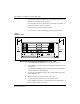
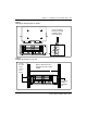
3 Connect the other end of the DS-1/E1 cable to the far end.
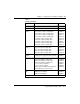
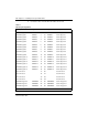
Table 2
DS-1/E1 pin assignment
Description Signal Pin Pin Signal Description
transmit tip port 0 TXTIPC0 1 40 RXTIPCO receive tip port 0
transmit tip port 1 TXTIPC1 2 41 RXTIPC1 receive tip port 1
transmit tip port 2 TXTIPC2 3 42 RXTIPC2 receive tip port 2
transmit tip port 3 TXTIPC3 4 43 RXTIPC3 receive tip port 3
transmit tip port 4 TXTIPC4 5 44 RXTIPC4 receive tip port 4
transmit tip port 5 TXTIPC5 6 45 RXTIPC5 receive tip port 5
transmit tip port 6 TXTIPC6 7 46 RXTIPC6 receive tip port 6
transmit tip port 7 TXTIPC7 8 47 RXTIPC7 receive tip port 7
transmit tip port 8 TXTIPC8 9 48 RXTIPC8 receive tip port 8
transmit tip port 9 TXTIPC9 10 49 RXTIPC9 receive tip port 9
transmit tip port 10 TXTIPC10 11 50 RXTIPC10 receive tip port 10
transmit tip port 11 TXTIPC11 12 51 RXTIPC11 receive tip port 11
transmit tip port 12 TXTIPC12 13 52 RXTIPC12 receive tip port 12
transmit tip port 13 TXTIPC13 14 53 RXTIPC13 receive tip port 13
transmit tip port 14 TXTIPC14 15 54 RXTIPC14 receive tip port 14
transmit tip port 15 TXTIPC15 16 55 RXTIPC15 receive tip port 15
not connected 17 56 not connected
not connected 18 57 not connected
not connected 19 58 not connected
not connected 20 59 not connected
transmit ring port 0 TXRINGC0 21 60 RXRINGC0 receive ring port 0
transmit ring port 1 TXRINGC1 22 61 RXRINGC1 receive ring port 1
transmit ring port 2 TXRINGC2 23 62 RXRINGC2 receive ring port 2
(Sheet 1 of 2)