
Network Router User's Manual

Chapter 6 LEDs: support and diagnostic functions 63
Setting Up the BayStack Instant Internet 400-S Unit
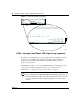
LEDs 1 through 8 and the Power LED during operation
After the power-up sequence is complete, the LEDs indicate status and activity
during operation as shown in Table 11.
Using the seven-port autosensing switch LEDs for
troubleshooting
The seven-port autosensing switch has two LEDs for each port on the switch. The
top row of these LEDs displays speed, link, and activity. The bottom row of LEDs
displays whether the unit is operating in full- or half-duplex mode.
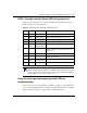
Table 11 LED status and appearance during operation
LED # Color Appearance Meaning
Power Green Solid Unit has electrical power and is turned on.
Power Green and
Amber
Solid Green and
Flashing Amber
Unit is updating flash ROM. DO NOT TURN
THE UNIT OFF until light returns to green.
1 Green Blinking Unit is operating normally.
2 Green Solid Unit is ready to service clients.
2 Green and
Amber
Solid Green and
Flashing Amber
Unit is communicating with clients.
2 Amber Solid Unit is ready to run setup but cannot service
clients (normally occurs before unit has been
configured).
3-8 Green Solid Indicated interface (see Note below) is online.
3-8 Green Flashing Indicated interface (see Note below) is dialing or
attempting connection.
3-8 Green and
Amber
Solid Green and
Flashing Amber
Traffic is on the indicated interface.
3-8 Red Solid Indicated interface (see Note below) has failed.
Note: The “indicated interface” is the interface associated with the
LED’s number. This information is available in the main dialog box of the
Setup program. For more information, refer to Using the BayStack Instant
Internet Management Software Version 7.11.