Part No.
Copyright © 2000 Nortel Networks All rights reserved. April 2000. The information in this document is subject to change without notice. The statements, configurations, technical data, and recommendations in this document are believed to be accurate and reliable, but are presented without express or implied warranty. Users must take full responsibility for their applications of any products specified in this document. The information in this document is proprietary to Nortel Networks NA Inc.
Japan/Nippon Requirements Only Voluntary Control Council for Interference (VCCI) Statement Taiwan Requirements Bureau of Standards, Metrology and Inspection (BSMI) Statement Canada Requirements Only Canadian Department of Communications Radio Interference Regulations This digital apparatus (Passport 8010 Chassis) does not exceed the Class A limits for radio-noise emissions from digital apparatus as set out in the Radio Interference Regulations of the Canadian Department of Communications.
iv
About this Guide This guide provides information about installing and using the Passport™ 8010 Chassis.
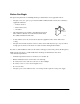
Before You Begin The physical requirements for installing the Passport 8010 Chassis in an equipment rack are: • Adequate room (13.1 spaces) is provided in an EIA or IEC standard 19-inch (48.2-centimeter) equipment rack that is: — Bolted to the floor — Braced if necessary — Grounded • Side rail dimensions are similar to this illustration. Typical racks with these dimensions are the Chatsworth Products, Inc. (CPI) rack and the B-Line rack. 3 in = 7.6 cm 9114FA • At least 6 inches (15.
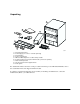
Unpacking 1 3 2 4 5 6 7 8 9 9073FA 1 = Passport 8010 Chassis 2 = Power Supply (one or more—ordered separately) 3 = Documentation 4 = Power cord (optional) 5 = DB-25 to DB-9 adapter for use with comm port cable 6 = Comm port cable for Passport 8132TX module, purchased separately 7 = Rack mounting brackets 8 = Screws for brackets and equipment rack 9 = Cable guides For detailed information about the comm port cable for the Passport 8132TX Switch Module, refer to the documentation that was shipped wit
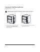
Attaching the Rack-Mounting Brackets Required tool: Phillips screwdriver Note: Each bracket fits only one side of the chassis. If the mounting holes do not line up between a bracket and the chassis, try that bracket against the other side of the chassis. 9103FA 1. 4 Hold each rack-mounting bracket against one side of the chassis. Make sure the attachment holes in the bracket match the holes in the chassis. 9104FA 2. Insert the supplied flat-head screws to fasten each bracket to the chassis.
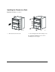
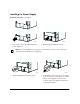
Installing the Chassis in a Rack Required tool: Phillips screwdriver 9074FA 1. Slide the chassis into the rack. 9075FA 2. Insert and tighten the rack-mounting screws. To complete the installation process, refer to “Installing the Power Supply.
Installing the Power Supply Required tool: Phillips screwdriver 8957FA 1. If necessary, remove the filler panel from a power supply bay. 8958FA 2. Push the supply firmly into the bay. Note: If you are installing a power supply in a new chassis, be sure to remove the bag of dessicant from the middle power supply bay. 8959FA 3. Align and tighten the retaining screws. 8960FA 4.
8964FA 5. Turn on the power switch. Note: In a newly installed chassis that requires two power supplies (nonredundant configuration), you must turn on both units within 2 seconds of each other. If you wait longer to turn on the second power supply, both power supplies will turn off. To correct this condition, turn off both power supplies, wait at least 30 seconds, and turn both power supplies on again within 2 seconds.
Attaching a Cable Guide Attach the cable guides to the left side of the chassis so the bundled cables will not obstruct airflow to the right side of the chassis. 9105FA 1. Loosen, but do not remove, the rack-mounting screws needed to install one cable guide. 9107FA 3. 8 Tighten the screws to secure the guide to the chassis. 9106FA 2. Slide the guide onto the loosened screws.
Installing a Module For details about the operation of modules, refer to the documentation that was shipped with each module. Required tool: Phillips screwdriver 9058FA 1. Remove a filler panel from a module slot. 9059FA 2. 9060FA 3. Align the module circuit board with the card guides in the chassis. Slide the module into a slot in the chassis until the module touches the backplane connectors. Make sure the inserter/extractor levers are rotated away from the front of the module. 9070FA 4.
9071FA 5. Align and tighten the retaining screws. Chassis Specifications Environmental Specifications Operating temperature: 0° to 40° C (32° to 104° F) Storage temperature: –25° to 70° C (–13° to 158° F) Operating humidity: 85% maximum relative humidity, noncondensing Storage humidity: 95% maximum relative humidity, noncondensing Operating altitude: 3,024 m (10,000 ft) Physical Specifications Height: 22.9 in. (58.2 cm) Width: 17.5 in. (44.5 cm) Depth: 19.9 in. (50.
Electrical Specifications System Line Frequency 47 to 63 Hz System with one power supply or two supplies in redundant configuration: Input Volt Amperes Rating: 1,236 VA maximum Input Power: 1,112 W maximum Input Voltage: 100-240 VAC Input current: 12 to 6 A per line cord Thermal rating: 3,792 BTU per hour maximum System with two power supplies (nonredundant) or three supplies in redundant configuration: Input Volt Amperes Rating: 2472 VA maximum Input Power: 2224 W maximum Input Voltage: 100-240 VAC Input
12