
Business Policy Switch User Guide

Chapter 5 Sample QoS configuration 301
Using the Business Policy Switch 2000 Version 1.2
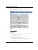
This address is used to match the destination IP address in the packet’s IP
header.
b In the Subnet Mask field, enter
255.255.255.0.
3 In the Source Address box, click Network Address.
a In the Network Address field, enter
134.177.0.0.
This is the IP address to match against the packet’s source IP address.
b In the Subnet Mask field, enter
255.255.0.0.
4 In the DSCP field, choose
0x20 from the list.
This value matches packets with a DSCP of 0x20 (32 decimal value).
If you choose Ignore, the DSCP value in the packet is ignored.
5 In the Protocol field, choose
TCP from the list.
When you select TCP, you specify that only TCP packets be matched. If you
select Ignore, all IP protocols are matched.
6 In the Destination Layer 4 Port field, click Ignore.
7 In the Source Layer 4 Port field, click Ignore.
8 Click Submit.
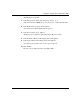
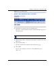
The new entry appears in the IP Filter Table.
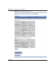
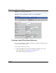
Creating an IP Filter Group Table entry
Now you can create an IP filter group in the IP Filter Group Table section of the IP
Classification page.
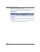
To create an IP filter group entry:
1 Click Create Filter Group in the IP Filter Group Table section of the IP
Classification page.
The IP Classification Group page opens (Figure 107).