Nortel CallPilot Quickstart Guide NN44200-313 .
Document status: Standard Document version: 01.02 Document date: 19 May 2008 Copyright © 2007-2008, Nortel Networks All Rights Reserved. Sourced in Canada. Information is subject to change without notice. Nortel Networks reserves the right to make changes in design or components as progress in engineering and manufacturing may warrant. The process of transmitting data and call messaging between CallPilot and its servers, switches or system is proprietary to Nortel Networks.
HITACHI is a trademark of Hitachi Limited. LOGITECH is a trademark of Logitech, Inc. LUCENT is a trademark of Lucent Technologies, Inc. MATRA is a trademark of Matra Hachette. MCAFFEE and NETSHIELD are trademarks of McAfee Associates, Inc. MYLEX is a trademark of Mylex Corporation. NET2PHONE is a trademark of Net2Phone, Inc. NETOPIA is a trademark of Netopia, Inc. NETSCAPE COMMUNICATOR is a trademark of Netscape Communications Corporation. NOTES is a trademark of Lotus Development Corporation.
Contents How to get help 7 Getting help from the Nortel Web site 7 Getting help over the phone from a Nortel Solutions Center 7 Getting help from a specialist by using an Express Routing Code 7 Getting help through a Nortel distributor or reseller 8 CallPilot 5.0 installation Prerequisites to CallPilot 5.0 installation CallPilot 5.
Contents 1005r CallPilot server Front panel 33 Back panel 35 33 CallPilot server preinstallation Recommended tools 37 CallPilot server preinstallation tasks Choosing a location 38 Preparing the site 38 Connecting to the network 39 Unpacking the server 39 37 38 CallPilot server installation CallPilot server installation tasks 41 Rack-mounting the server 41 Installing peripheral devices 42 Installing cables and grounds 43 Performing preboot checks 45 Connecting the server to power and starting it 41
How to get help This chapter explains how to get help for Nortel products and services. Getting help from the Nortel Web site The best way to get technical support for Nortel products is from the Nortel Technical Support Web site: www.nortel.com/support This site provides quick access to software, documentation, bulletins, and tools to address issues with Nortel products.
How to get help www.nortel.com/erc Getting help through a Nortel distributor or reseller If you purchase a service contract for your Nortel product from a distributor or authorized reseller, you can contact the technical support staff for that distributor or reseller. Nortel CallPilot Quickstart Guide NN44200-313 01.02 Standard 5.0 19 May 2008 Copyright © 2007-2008, Nortel Networks .
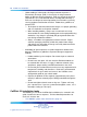
CallPilot 5.0 installation The CallPilot 5.0 Quickstart Guide provides basic instructions on new hardware installation and basic configuration of a CallPilot 5.0 system. After using this guide to set up a basic CallPilot configuration, you should be able to dial a mailbox, leave a message and retrieve a message using the telephone. For more detailed configuration information, see the appropriate technical documentation.
CallPilot 5.0 installation • Understanding of electrostatic discharge and how to prevent it. Electrostatic discharge (ESD) is the transfer of charge between bodies at different electrical potentials. ESD can change the electrical characteristics of a semiconductor device and degrade or destroy it. ESD can also disrupt the normal operation of an electronic system by causing equipment malfunction or failure.
Time requirements • "CallPilot resource configuration" (page 17) • "CallPilot server preinstallation" (page 37) • "CallPilot server installation" (page 41) • "CallPilot server configuration" (page 47) • "CallPilot server testing" (page 55) 11 Time requirements The following table shows the approximate time required to complete each task in the work flow.
CallPilot 5.0 installation Nortel CallPilot Quickstart Guide NN44200-313 01.02 Standard 5.0 19 May 2008 Copyright © 2007-2008, Nortel Networks .
CS 1000/M1 system status check This task describes how to check the Communication Server 1000 (CS 1000) or the Meridian 1 (M1) system status. To successfully install a basic CallPilot system, you must provision or verify the following parameters on the telephony switch (CS 1000 or M1): • PBX IP and host name • VAS ID • ELAN ID • system parameters • ACD • DFDN • CDN • ACD agents • telephones CallPilot can be provided only on a per-customer basis on the CS 1000 or M1 system.
CS 1000/M1 system status check • "Checking the status of the ELAN connection to the PBX (LD 48)" (page 15) Checking the current IP address of the PBX (LD 117) Perform the following procedure to check the current IP address in the CS 1000 or M1 system. Step Action 1 Connect to the PBX. 2 If you have not already done so, log on using the proper account with the following syntax: logi 3 Press Enter. 4 At the prompt, type the password for the login name and press Enter.
Checking the status of the ELAN connection to the PBX (LD 48) 15 —End— Checking the ELAN interface status of the PBX (LD 137) Perform the following procedure to check the ELAN interface status. Step Action 1 Connect to the PBX. 2 Enter LD 137. 3 Enter STAT ELNK. The status of the ELAN interface appears. Note: If the ELAN interface is not configured, continue to "Enabling the ELAN interface of the PBX (LD 137)" (page 15).
CS 1000/M1 system status check Step Action 1 Connect to the PBX. 2 Enter LD 48. 3 Enter STAT ELAN to display a list of current AML links. Note: Take note of any enabled and active ELANs. This will be useful when deciding if a new VAS ID and ELAN ID are required. 4 To exit the overlay, enter ****. —End— Nortel CallPilot Quickstart Guide NN44200-313 01.02 Standard 5.0 19 May 2008 Copyright © 2007-2008, Nortel Networks .
CallPilot resource configuration This task describes how to configure CallPilot 5.0 resources on the Communication Server 1000 (CS 1000) or Meridian 1 (M1) system. CallPilot can be provided only on a per-customer basis on the CS 1000 or M1 system. AML messages used for communications between the telephony switch and CallPilot contain a customer number to which CallPilot belongs. In these procedures, ensure that you enter the correct customer number in the overlays.
CallPilot resource configuration Configuring a new ELAN ID and VAS ID (LD 17) Define and configure the ELAN subnet for the AML link and its associated VAS ID in the configuration record. This provides the Ethernet connection over which AML messages are exchanged between the CS 1000 or M1 system and CallPilot. A separate ELAN must be created for CallPilot and Contact Center for the purpose of integration. Perform this procedure only if there is no VAS ID provisioned or available.
Configuring system parameters (LD 17) Prompt Response Notes ELAN xx Enter the number entered for the ELAN ID above. SECU YES 5 19 To exit the overlay, enter ****. Tech tip: To view the new ELAN, enter LD 22. Enter PRT at the REQ prompt, then ADAN. A list of all provisioned IDs appears. Use the capture text function in hyperterminal to save a text file of the output.
CallPilot resource configuration Prompt Response Notes CSQI xxx Enter the number of CallPilot DS0 channels multiplied by 2. For example, if there are 24 DS0 channels, enter 48. xxx CSQO Enter the number of CallPilot DS0 channels multiplied by 2. For example, if there are 24 DS0 channels, enter 48. 4 To exit the overlay, enter ****.
Defining CallPilot in the customer data block (LD 15) 4 21 Enter the appropriate values as described in the following table to define Call Redirection. For prompts not listed in the following table, press Enter to accept the default. Table 6 LD 15 - Configuring Call Redirection Prompt Response REQ CHG TYPE rdr CUST xx Customer number for CallPilot. FNAD xxxx Enter the FDN for CallPilot. FNAT xxxx Enter the FDN for CallPilot. FNAL xxxx Enter the FDN for CallPilot.
CallPilot resource configuration Table 8 LD 15 - Configuring Integrated Services Digital Network Prompt Response Notes REQ CHG TYPE net CUST xx Customer number for CallPilot. ISDN YES Enter NO if NMS is not installed on the CS 1000 or M1 system. NO xxxxx PNI Private Network Identifier. Within one network, use the same PNI value in LDs 15 and 16.
Configuring Automatic Call Distribution (LD 23) 3 23 Enter the appropriate values as described in the following table. For prompts not listed in the following table, press Enter to accept the default. Table 9 LD 16 - Configuring the Route Data Block Prompt Response REQ CHG TYPE rdb CUST xx Customer number for CallPilot. ROUTE xxx Enter the number of the route you wish to modify. DES aaa Description for the route. IDEF LOC RCLS EXT 4 Notes To exit the overlay, enter ****.
CallPilot resource configuration Table 10 LD 23 - Configuring Automatic Call Distribution Prompt Response REQ NEW TYPE ACD CUST xx Customer number for CallPilot. ACDN xxxx This is the ACD DN the agents point at. MWC NO MAXP xxxx CALP POS IVR YES ALOG YES 4 Notes Maximum number of agent channels. To exit the overlay, enter ****. —End— Configuring the DFDN (LD 23) Before you configure the CDN queue, define the default ACD DN to be referenced in the CDN.
Configuring the CDN queue (LD 23) 25 Table 11 LD 23 - Configuring DFDN Prompt Response Notes REQ NEW TYPE ACD CUST xx Customer number for CallPilot. ACDN xxxx Enter the DFDN. MWC NO MAXP 1 Maximum number of agent channels. Enter 1 to make this a DFDN queue. 0 NCFW 4 To exit the overlay, enter ****. —End— Configuring the CDN queue (LD 23) The control DN is the single point to which the end user calls to access voice mail or use multimedia functions such as fax capabilities.
CallPilot resource configuration Prompt Response TYPE CDN CUST xx Customer number for CallPilot. CDN xxxx Control DN of the CallPilot system (for example, 4300). DFDN xxxx The default ACD created above, in the procedure "Configuring the DFDN (LD 23)" (page 24). 4 Notes To exit the overlay, enter ****. —End— Configuring ACD agents (LD 11) For CallPilot, you must define channels as ACD agents on M2008 digital sets. All agents are added to the configured ACD queues.
Provisioning telephones (LD 11) 27 Prompt Response Notes TN aaa.bbb.ccc.ddd Terminal Number, where a = loop, b = shelf, c = MGATE card slot, d = channel for that card (0–31). DES dddddd Description. CUST xx Customer number for CallPilot. CLS WTA UNR VCE MMA FLAX KEY 0 ACD xxxx 0 yyyy xxxx = the ACD defined above in the procedure "Configuring Automatic Call Distribution (LD 23)" (page 23).
CallPilot resource configuration 2 Enter LD 11. 3 Enter the appropriate values as described in the following table. For prompts not listed in the following table, press Enter to accept the default. Table 14 LD 11 - Provisioning telephones Prompt Response REQ NEW TYPE a..a Notes Telephone type For example: i2004 TN aaa.bbb.ccc.ddd Terminal Number, where a = loop, b = shelf, c = card slot, d = card channel (0–31). For example: 66 0 0 10 IP Phones require a VGMC card.
Enabling card slots (LD 32) 29 Prompt Response Notes KEY 0 SCR xxxx Where xxxx is the line number of the telephone. This is the number dialled or the line selected when the user makes a call from the telephone. For example: 4710 KEY 16 MWK xxxx Where xxxx is the CDN of the CallPilot system. For example: 4300 4 Repeat step 3 for each telephone to be configured. Configure at least two telephones for testing purposes. 5 To exit the overlay, enter ****.
CallPilot resource configuration 6 To exit the overlay, enter ****. —End— Saving CS 1000/M1 changes (LD 43) Perform the following procedure to save all configuration changes. If a reboot occurs before you save the system, all your changes could be lost. Tech tip: The prompt for LD 43 is just a period ".". Entering the command EDD will complete a data dump to the on board flash. Step Action 1 Connect to the PBX. 2 Enter LD 43. 3 At the "." prompt, enter EDD. 4 To exit the overlay, enter ****.
CallPilot server general description This section describes the hardware components of the CallPilot servers. For CallPilot Release 5.0, there are two server models: the 600r CallPilot server and the 1005r CallPilot server. The 600r system is a small-capacity system that can handle up to 20,000 mailboxes. The 1005r is a large-capacity system that can handle up to 50,000 mailboxes. Both servers are rack-mounted servers that fit into a standard 19” or 23” rack.
CallPilot server general description Figure 2 600r CallPilot server - front panel LEDs Table 15 600r CallPilot server - front panel LEDs Label Description A Power button B Reset button C Critical fault LED D Major fault LED E Minor fault LED F Power LED G Disk 0 activity/fault LED (green/amber) H Not used I Main power LED (green) J NIC activity LED (green) K System ID LED (white) L ID button M NMI button (not used) Back panel Figure 3 "600r CallPilot server - back panel" (pag
1005r CallPilot server 33 Figure 3 600r CallPilot server - back panel Table 16 600r CallPilot server - back panel controls and features Label Description A USB 0, USB1, USB2 (bottom to top) B PS/2 mouse input C SCSI port (requires terminator) D MPB96 card E Power supply F AC power input G Ground studs H ELAN input I Nortel server subnet (CLAN) input J Video input K COM1 DB-9 serial port L PS/2 keyboard input 1005r CallPilot server Front panel Figure 4 "1005r CallPilot server - f
CallPilot server general description Figure 4 1005r CallPilot server - front panel Table 17 1005r CallPilot server - front panel LEDs and controls Label Description A Power button B Reset button C Critical alarm LED D Major alarm LED E Minor alarm LED F Power alarm LED G NMI switch (not used) H ID switch I ID LED J NIC activity LED K Status LED L Hard drive 1 activity and status M Hard drive 0 activity and status N DVD/CD/CD-RW O RJ45 COM1 serial port P USB 2 Q ESD con
1005r CallPilot server Label Description R Hard drive 1 pull handle S Hard drive 1 release lever T Hard drive 0 pull handle U Hard drive 0 release level 35 Back panel Figure 5 "1005r CallPilot server - back panel" (page 35) shows the back panel on the 1005r. The back panel controls and features are described in Table 18 "1005r CallPilot server - back panel controls and features" (page 35).
CallPilot server general description Label Description L USB 0 (dongle connects here) M Server management LAN port N SCSI port (does not require terminator) Nortel CallPilot Quickstart Guide NN44200-313 01.02 Standard 5.0 19 May 2008 Copyright © 2007-2008, Nortel Networks .
CallPilot server preinstallation This task describes the CallPilot server preinstallation.
CallPilot server preinstallation CallPilot server preinstallation tasks The following is a list of tasks you perform to prepare for CallPilot server installation. To link to detailed procedures for each task, click the text.
Unpacking the server 39 4 Install the rack, or ensure that a pre-existing rack is properly installed with sufficient space for the CallPilot server and peripheral devices. The 600r is a 1U form factor and the 1005r is a 2U form factor. 5 Ensure that an external analog phone line is available for the USB modem. 6 Ensure that a single-point ground reference is available for all the power outlets serving the CallPilot server and its peripherals.
CallPilot server preinstallation • monitor • keyboard • mouse • USB modem • Tandberg tape drive • tapes • SCSI cable • power cords Place the peripheral devices in a safe, secure area near the installation site.
CallPilot server installation This task describes the CallPilot server installation. CallPilot server installation tasks The following is a list of tasks you perform to install the CallPilot server. To link to detailed procedures for each task, click the text.
CallPilot server installation 5 Tighten all the nuts that you previously hand-tightened. 6 Slide the system into the rack. Check that the inner rail fits together with the outer rail. 7 To secure the server in place, install screws in the front-tab mounting bracket to the rail. For a two-post install, install four screws through the clearance slots in the side of the outer rail assembly into the inner rail.
Installing cables and grounds 43 6 Set the SCSI ID on the tape drive to 6. 7 Install the monitor, keyboard, and mouse in the same location as the server. If you are using a KVM-type box, ensure that you have visual contact with the LEDs on the CallPilot server. 8 Plug the keyboard and mouse cables into the PS/2 connectors on the rear panel according to the labels. 9 Plug the monitor into the video connector on the rear panel. Tighten screws on the connector.
CallPilot server installation 3 Install the power cords to all devices, but plug them only into the receptacle, not into the end device.
Connecting the server to power and starting it 6 45 Install and connect the DS30X cable from the switch MGATE card to the CallPilot MPB96, starting from the switch side. The following are guidelines: • The 3 connectors of each DS30X cable going to the MGate card are labeled with DS30X-1 to DS30X-3. Connect the DS30X-1 first, the DS30X-2 second, and the DS30X-3 third. This is important for timing off the MGATE card.
CallPilot server installation Step Action 1 Plug the power cords into all peripheral devices, including the monitor, tape drive, and Ethernet switch or hub as applicable to system setup. 2 Turn on all peripheral devices. 3 Plug the power cords into the CallPilot server. Check that the status LEDs on the power supply are lit green. 4 Do one of the following: • For the 1005r server, push the power switch on the front panel to power on the server.
CallPilot server configuration This task describes the CallPilot server configuration. CallPilot server configuration tasks The following is a list of tasks you perform to configure the CallPilot server. To link to detailed procedures for each task, click the text.
CallPilot server configuration 3 In the Service Update (SU)/PEP Installation page, select Yes, I have updates that I want to install now. 4 Click Next. A message appears, prompting you to install SUs and PEPs. 5 Browse to the PEP CD in the DVD-ROM (Z:) drive. For every PEP or SU to be installed, review the readme file for important steps required for the PEP or SU.
Running the Configuration Wizard 49 Running the Configuration Wizard This procedure covers basic provisioning only. You can perform additional provisioning and advanced configuration, such as media allocation, channels, CDNs, and languages, after completing the basic provisioning steps in this procedure. Alternatively, you can run the Configuration Wizard at any time to make configuration changes or add additional information.
CallPilot server configuration a. Type the Computer name. b. Select the Time Zone. c. Type the Area Code and Country Code. d. Type the LDAP search base. e. Click Next. 10 On the Password Information page, when prompted, change the administrator password for the workstation local login as follows: a. Type a new password (secure format required). b. Type the new password again. c. Click Next. d. If a warning message appears, click OK. 11 In the Multimedia Allocation page, click Next.
Running the Configuration Wizard 51 a. In the CND box, type the CDN configured in the procedure "Configuring the CDN queue (LD 23)" (page 25). b. From the Application Name list, select Voice Messaging. c. Click OK. 15 In the CND Information page, click Next. 16 Insert the CallPilot 5.0 Language CD into the DVD drive. 17 In the Language Source Directory page, do the following: a. Select the Install Language option. b. In the Language CD Location box, type Z:. c. Click Next.
CallPilot server configuration 21 When the configuration is complete, restart the CallPilot server. —End— Configuring new mailboxes and additional tasks Perform the following procedure to create new mailboxes on the CallPilot server. In this procedure, you create two test mailboxes. Creating additional mailboxes and other items adds additional time to the installation. Step Action 1 Log on to the CallPilot server using the new password you configured in the previous procedure.
Backing up the system 8 53 In the Channel Monitor page, under Channel Status, check that two channels are shown in dark blue indicating an idle status. Tech tip: If a channel status is red, check the DS30 cabling and then check the telephony switch provisioning. A cable may be plugged into the wrong slot or a card may be disabled or not provisioned. —End— Backing up the system Note: At this point, a backup is recommended but not necessary.
CallPilot server configuration b. In Select the specific date and time. , select the current date and time using the 24-hour clock. c. In the Description box, type a relevant description of the backup. d. Click Next. 6 In the Confirm Schedule page, review the backup information, and then click Finish. 7 In the Backup/Restore page, select the backup profile you just created and click Backup Now. 8 In the message that prompts you to start the backup immediately, click OK.
CallPilot server testing This task describes how to test the CallPilot server. CallPilot server testing tasks The following is a list of tasks you perform to test the CallPilot server. To link to detailed procedures for each task, click the text.
CallPilot server testing 2 • Check the provisioning, to ensure the PBX is on the same subnet. • Check the provisioning of the telephony switch. To check the CLAN connectivity, do the following: a. From the CallPilot server console, click Start > Run. b. Type cmd, and then click OK. The command prompt appears. c. Type ping [IP address of your Nortel server subnet Gateway], and then press Enter. For example, ping 192.167.249.1 Tech tip: You should get ping replies back from the Gateway.
Verifying that each CallPilot channel is functioning correctly 57 3 Type the test mailbox number for the telephone you are on, followed by the # key. 4 Type the password for the mailbox, followed by the # key. The default password is 12 + mailbox number. For example, if the mailbox number is 4500 the password is 124500. 5 When prompted, type a new password, followed by the # key. Re-enter the new password followed by the # key to confirm the changed password.
CallPilot server testing Step Action 1 Log on to CallPilot Manager on the local console. 2 In the CallPilot Manager toolbar, select Maintenance > Channel Monitor. 3 From both test telephones, simultaneously dial the CallPilot voice messaging CDN. Call from one test telephone and leave it off the hook while you dial from the other, so that both channels are occupied at the same time. If you have other channels that require testing, stop all other channels except the ones being tested.
What is next? 59 What is next? For advanced configuration and provisioning information, refer to the following NTPs: • Administrator Guide (NN44200-601) and CallPilot Manager online Help • Software Administration and Maintenance (NN44200-600) • Desktop Messaging and My CallPilot Installation and Administration (NN44200-305) • 600r Server Hardware Installation (NN44200-307) • 600r Server Maintenance and Diagnostics (NN44200-703) • 1005r Server Hardware Installation (NN44200-306) • 1005r Server
CallPilot server testing Nortel CallPilot Quickstart Guide NN44200-313 01.02 Standard 5.0 19 May 2008 Copyright © 2007-2008, Nortel Networks .
Appendix Installing the CallPilot 5.0 image The CallPilot 5.0 software comes preinstalled from the factory. If the installed image becomes corrupted, perform this procedure to install the CallPilot 5.0 image again. Installing the CallPilot 5.0 image Step Action 1 Insert the CallPilot Image DVD for the platform type you are recovering into the DVD drive. 2 Using the button on the front panel of the server, power the server off, and then power it back on. 3 Select 1. Install CallPilot 5.
Appendix Installing the CallPilot 5.0 image The server starts the Windows 2003 configuration. During the Windows 2003 configuration, the server restarts several times. After the last restart sequence, the Windows login dialog appears. 8 Return to "CallPilot server configuration" (page 47). —End— Nortel CallPilot Quickstart Guide NN44200-313 01.02 Standard 5.0 19 May 2008 Copyright © 2007-2008, Nortel Networks .
Appendix Configuring phantom DNs This appendix describes how to configure phantom DNs. There are two reasons to configure phantom DNs on the switch: • to create a dialable number for CallPilot services such as Application Builder configurations and voice forms • to create virtual fax DNs for users who want a separate fax number Checking for existing phantom loops Step Action A phantom loop must exist before you begin to configure phantom DNs. Use this procedure to identify a phantom loop.
Appendix Configuring phantom DNs 2 Enter LD 97. 3 At the REQ prompt, enter CHG. 4 At the TYPE prompt, enter SUPL. 5 At the SUPL prompt, enter xxxx, where xxxx is the loop number, prefixed with N to designate the loop as a phantom loop, or with V to designate a virtual loop. For Large Systems, xxxx = N0–N156 in multiples of 4. For Small Systems, xxxx = N96 - N112 in multiples of 4. 6 To exit the overlay, enter ****. —End— Creating a phantom DN Step Action 1 Connect to the PBX.
Creating a phantom DN Prompt Response CLS WTA 65 Notes UNR FTR DCFW nn xxxx Note: After you type the response and press Enter, the ftr prompt appears again. To continue, press Enter again. —End— Nortel CallPilot Quickstart Guide NN44200-313 01.02 Standard 5.0 19 May 2008 Copyright © 2007-2008, Nortel Networks .
Nortel CallPilot Quickstart Guide Copyright © 2007-2008, Nortel Networks All Rights Reserved. Publication: NN44200-313 Document status: Standard Document version: 01.02 Document date: 19 May 2008 To provide feedback or report a problem in this document, go to www.nortel.com/documentfeedback. Sourced in Canada. The information in this document is subject to change without notice.