
User's Manual


Chapter 3 Physical installation 29
BCM 4.0 Installation Checklist and Quick Start Guide
Wiring the FEM
A fiber expansion module (FEM) allows you to upgrade from a Norstar system to a BCM system
by reusing the Norstar MBMs. The MBMs connect to the FEM using the same fiber cable that
connected them to the Norstar fiber expansion card.
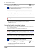
To connect the fiber cables
1 Ensure the BCM system is powered up and functional.
2 Connect the fiber cables from the Norstar MBMs to the jacks on the FEM.
a Connect the Norstar Line Modules to the FEM beginning at fiber port 1.
b Connect Norstar Extension Modules to the FEM beginning at fiber port 6.
3 Change the DN records in Element Manager or change the set wiring, as required, to match
your system.
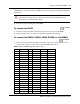
Powering up the BCM system
Refer to the chapter “Connecting the cables” in the BCM200/400 4.0 Installation and Maintenance
Guide for more detailed information.
Warning: Handling optical fiber cables.
If the cable is too long, ensure that it is coiled correctly using the fiber spool. Coil excess
fiber cable carefully around the spool provided. Do not bend the cable around any tight
corners. Bends in the fiber cable must not be less than 100 mm in diameter. Place the fiber
cable spool into a slot at the back of the cable trough in the Norstar module.
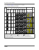
Note: The DIP switch settings you chose determine which FEM ports are available. If you
enable all six FEM ports, the BCM system has no more DS30 resources available.
Therefore, you cannot connect more MBMs to the system.
Note: If you connect a Norstar station module amphenol cable directly to a DSM, you do
not have to modify the wiring connections. Ensure you select the correct DS30 number.
Caution: The BCM system is available in North American and International
versions. Ensure that the power supply is correct for your location. The BCM200
and BCM400 systems have standard power supplies and redundant power
supplies that adjust automatically to the required voltage.
2 minutes/MBM