
User's Manual


28 Chapter 3 Physical installation
N0060602N0060602
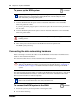
2 Install the telephones and peripheral equipment (if it is a new system):
a Attach the cables for the telephones to the connecting blocks.
b Install the telephones.
3 Plug the female amphenol connector into the interface on the front of the MBM.
4 Set up any mobile system you are using.
• Ensure the base stations are correctly installed and connected to the appropriate MBMs on
the BCM system. In the case of the Wireless LAN IP phone system, ensure that the access
point is correctly set up to connect to the BCM system LAN or WAN.
• Configure and register the handsets according to the instructions provided for each type of
system.
11 Blue-Black X11 11 27 –
37 Black-Orange X12 12 28 –
12 Orange-Black X12 12 28 –
38 Black-Green X13 13 29 –
13 Green-Black X13 13 29 –
39 Black-Brown X14 14 30 –
14 Brown-Black X14 14 30 –
40 Black-Slate X15 15 31 –
15 Slate-Black X15 15 31 –
41 Yellow-Blue X16 16 32 –
16 Blue-Yellow X16 16 32 –
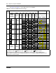
For ASM only
34-50
9-25
no connection
For DSM only
42-50
17-25
no connections
1
Single connector, or bottom connector on DSM 32/32+ modules.
2
Upper connector on DSM 32/32+ modules.
Table 8 ASM and DSM wiring chart (Sheet 2 of 2)
Pin Wire color Port
1
DSM Set #
2
DSM Set # ASM Set #