
User's Manual


Chapter 3 Physical installation 27
BCM 4.0 Installation Checklist and Quick Start Guide
All MBMs have an auxiliary jack (the CTM8 has two). Do not attempt to plug digital equipment
into this jack.
3 Insert the connector into the jack on the MBM.
To connect the GATM
1 Connect one end of the cable to the amphenol connector on the front of the MBM.
2 Connect the other end of the cable to the demarcation blocks of the building.
To connect the DSM16, DSM32, ASM8, GASM8, or 4x16 MBMs
1 Connect 16 wire pairs from the amphenol connector to the local connecting blocks so they
connect to the 16 stations you want connected to this MBM (see Table 8).
Warning: The BRIM S/T must only be connected to an NT1 provided by the service
provider. The NT1 must provide a Telecommunication Network Voltage (TNV) to
Safety Extra Low Voltage (SELV) barrier.
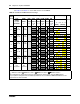
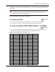
Table 8 ASM and DSM wiring chart (Sheet 1 of 2)
Pin Wire color Port
1
DSM Set #
2
DSM Set # ASM Set #
26 White-Blue X01 1 17 1
1 Blue-White X01 1 17 1
27 White-Orange X02 2 18 2
2 Orange-White X02 2 18 2
28 White-Green X03 3 19 3
3 Green-White X03 3 19 3
29 White-Brown X04 4 20 4
4 Brown-White X04 4 20 4
30 White-Slate X05 5 21 5
5Slate-WhiteX055 21 5
31 Red-Blue X06 6 22 6
6 Blue-Red X06 6 22 6
32 Red-Orange X07 7 23 7
7 Orange-Red X07 7 23 7
33 Red-Green X08 8 24 8
8 Green-Red X08 8 24 8
34 Red-Brown X09 9 25 –
9 Brown-Red X09 9 25 –
35 Red-Slate X10 10 26 –
10 Slate-Red X10 10 26 –
36 Black-Blue X11 11 27 –
2 minutes
15 minutes