
User's Manual


26 Chapter 3 Physical installation
N0060602N0060602
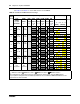
Figure 8 DTM RJ-48C wiring array
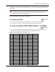
Figure 9 CTM RJ-11 wiring array
Figure 10 BRIM S/T RJ-45 wiring array
Warning: If you are using a service provider channel service unit (CSU), you must
disable the BCM system internal CSU.
1 2 3 4 5 6 7 8
DTM connector
To network To plug
Receive from
network
1- Rring
2 - Rtip
3 - Rshield
Transmit to network 4-Tring
5-Ttip
6-Tshield
RJ-48C jack
6 5 4 3 2 1
CTM
connector
RJ-11 jacks
Auxiliary jack
Pin #/connection
3- Ring
4 - Tip
The CTM8 has ten RJ-11 jacks, including two
auxiliary jacks.
The 4x16 and CTM4 media bay modules have
four RJ-11 jacks.
8 7 6 5 4 3 2 1
BRIM S/T connector
RJ45 jacks
Pin #/connection System side
1 not used
2 not used
3 +Rx
4 +Tx
5 -Tx
6 -Rx
7 not used
8 not used
+Tx
+Rx
-Rx
-Tx