
User's Manual


Chapter 3 Physical installation 25
BCM 4.0 Installation Checklist and Quick Start Guide
To connect the DTM, CTM, BRIM, or 4x16 MBMs
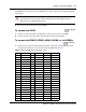
1 On the front of the MBM, locate the RJ-48C jack (DTM), RJ-45 jack (BRIM), or the RJ-11
jacks (CTM and 4x16).
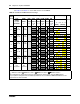
2 Connect one end of the cable to the demarcation blocks of the building (see Figure 8, Figure 9,
or Figure 10 for the appropriate pin-out).
Danger: Electrical shock hazards
Electrical shock hazards from the telecommunications network and AC mains are possible
with this equipment. To minimize risk to service personnel and users, the BCM system
must be connected to an outlet with a third wire ground. In addition, all unused slots must
have blank faceplates installed. The covers on all units must be in place at the completion
of any servicing.
Warning: Electrical shock warning.
The BCM MBMs have been safety approved for installation into BCM main units and
expansion units. It is the responsibility of the installer and user to ensure that installation
of the BCM hardware does not compromise existing safety approvals.
Before you open the BCM main unit or expansion unit ensure that the network cables are
unplugged and the unit is disconnected from the AC power source.
Station MBMs: The ports on these MBMs are meant to be connected only to approved
digital telephones and peripherals with the proper cables on a protected internal wiring
system.
Do not connect any telephones to wiring that runs outside of the building.
15 minutes