BCM 4.0 Installation Checklist and Quick Start Guide BCM 4.
Copyright © 2006 Nortel Networks, All Rights Reserved All rights reserved. The information in this document is subject to change without notice. The statements, configurations, technical data, and recommendations in this document are believed to be accurate and reliable, but are presented without express or implied warranty. Users must take full responsibility for their applications of any products specified in this document. The information in this document is proprietary to Nortel Networks.
SOFTWARE LICENSE NORTEL NETWORKS INC. (“NORTEL NETWORKS”) TELECOMMUNICATION PRODUCTS THIS LEGAL DOCUMENT IS A LICENSE AGREEMENT ("License") BETWEEN YOU, THE END-USER ("CUSTOMER") AND NORTEL NETWORKS. PLEASE READ THIS LICENSE CAREFULLY BEFORE USING THE SOFTWARE. BY USING THIS SOFTWARE, YOU, THE CUSTOMER, ARE AGREEING TO BE BOUND BY THE TERMS OF THIS LICENSE.
Except for Java Product (as defined herein below), CUSTOMER may assign collectively its rights under this License to any subsequent owner of the associated hardware, but not otherwise, subject to the payment of the then current license fee for new users, if any.
Contents 5 Contents Chapter 1 Getting started . . . . . . . . . . . . . . . . . . . . . . . . . . . . . . . . . . . . . . . . . . . . . . . . . 7 About this guide . . . . . . . . . . . . . . . . . . . . . . . . . . . . . . . . . . . . . . . . . . . . . . . . . . . . . . . 7 Purpose . . . . . . . . . . . . . . . . . . . . . . . . . . . . . . . . . . . . . . . . . . . . . . . . . . . . . . . . . . 7 Audience . . . . . . . . . . . . . . . . . . . . . . . . . . . . . . . . . . . . . . . . . . . . . . . . . .
Contents Connecting through the serial port . . . . . . . . . . . . . . . . . . . . . . . . . . . . . . . . . . . . 34 Downloading from the BCM web page . . . . . . . . . . . . . . . . . . . . . . . . . . . . . . . . . . . . 36 Generating a software keycode . . . . . . . . . . . . . . . . . . . . . . . . . . . . . . . . . . . . . . . . . . 37 Configuring the BCM system parameters . . . . . . . . . . . . . . . . . . . . . . . . . . . . . . . . . . 37 Startup Profile times and LED sequence . . . . . . . .
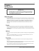
Chapter 1 Getting started IMPORTANT! Print this chapter to record the progress of the BCM system installation and configuration. The tables and checklists are valuable tools to guide you through the installation process. About this guide The BCM 4.0 Installation Checklist and Quick Start Guide describes how to install and configure BCM200 and BCM400 systems running Business Communications Manager (BCM) 4.0 software. Although not specifically covered in this document, BCM 4.
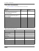
Chapter 1 Getting started The clock icon indicates that a procedure or task has been timed; the time is provided next to the icon. Installation and configuration summary Table 1 provides the tasks to install and configure a BCM system.
Chapter 1 Getting started 9 Table 1 Installation and configuration checklist (Sheet 2 of 2) ; Task Reference Comments 15 min. Configure the required BCM system parameters (Element Manager or Startup Profile) “Configuring the BCM system parameters” on page 37 1 min.
Chapter 1 Getting started Tools, data, and parameters Use Table 4 and Table 5 to record information about tools and information. Table 4 Tools Description Value Comments Laptop (or PC) with: • Windows 98 SE, Windows 2000, Windows XP • minimum 256 MB, recommended 512 MB • 150 MB free disk space Mounting hardware rack-mount brackets, wall-mount bracket, or rubber feet; an optional plywood backboard 3/4 in. (2 cm) thick for wall-mount installations.
Chapter 1 Getting started 11 Table 5 System information (Sheet 2 of 2) Description Value Comments V.90 modem settings (North America only) SNMP agent (security, version) SNMP manager IP address SNMP community string Checklists Before installing the BCM hardware, complete the following checklists (see the BCM200/400 4.0 Installation and Maintenance Guide for more information).
Chapter 1 Getting started Expansion unit and media bay modules components checklist 5 minutes Check that you have the following components, and inspect the components for any damage: F one expansion unit F one power supply cable F one expansion cable (use only supplied Ethernet cable) F four rubber feet F the correct media bay modules (MBM) N0060602
Chapter 2 System overview The BCM system includes the following primary hardware components and configuration tools: • • • • “Main units” on page 13 “BCM expansion unit (BCM400 only)” on page 14 “Element Manager” on page 15 “Startup Profile” on page 15 A BCM 4.0 system requires BCM 4.0 software operating on BCM200 or BCM400 hardware. Refer to the chapter “Introducing the BCM hardware” in the BCM200/400 4.0 Installation and Maintenance Guide for more detailed information.
Chapter 2 System overview Figure 2 BCM400 main unit ports and connectors RJ-48C WAN T1 WAN card (optional - North America version shown) Primary Mirror Page relay Auxiliary ringer Page output Music on hold Media services card input (MSC) DB26 connector (female) WAN Alarm Reset 4 MBM bays Master DS256 port COM port (serial port) Ethernet Ethernet Modem port port 2 port 1 (North America only) USB ports Note: Your system may not have all the cards indicated.
Chapter 2 System overview 15 Element Manager The primary management application for configuring and administering the BCM system is Element Manager. Element Manager is a client-based management application that runs on a Windows computer. You can connect to BCM system devices over an IP network and configure, administer, and monitor BCM system devices.
Chapter 2 System overview N0060602
Chapter 3 Physical installation This chapter provides the following installation procedures: • • • • • • • “Mounting a BCM main unit and expansion unit” on page 17 “Connecting the expansion unit to the main unit” on page 21 “Installing the MBMs” on page 21 “Connecting the MBM wiring” on page 24 “Powering up the BCM system” on page 29 “Connecting the data networking hardware” on page 30 “Unpacking, placing, and wiring telephone hardware” on page 31 Mounting a BCM main unit and expansion unit Before you
Chapter 3 Physical installation To attach the rack-mount brackets 6 minutes/unit 1 Place the BCM unit on a flat, clean surface. 2 Align the screw holes between the BCM unit and one of the rack-mount brackets. 3 Fasten the bracket to the BCM unit using four screws. Refer to Figure 4. Caution: Use only the screws supplied with the rack-mount bracket. Other screws can damage the unit. 4 Repeat steps 2 and 3 for the other rack-mount bracket.
Chapter 3 Physical installation 19 Figure 5 Fasten the BCM400 main unit to an equipment rack The BCM200 main unit and expansion unit are installed in a similar manner. 5 If the BCM system has an expansion unit, mount the expansion unit in the same way as the main unit. Installing a BCM unit on a wall To wall-mount a BCM unit (main unit or expansion unit), you need the optional wall-mount kit (NTAB3422).
Chapter 3 Physical installation 5 Align the screw holes on one side of the BCM unit with the wall-mount bracket. Note: The bracket suspends the BCM unit on the wall. Consider the direction you want the MBMs to face, left or right, when you choose the side on which to install the bracket. 6 Fasten the wall-mount brackets securely to the BCM unit using the screws provided. Refer to Figure 6. Caution: Use only the screws supplied with the wall-mount bracket kit (NTAB3422).
Chapter 3 Physical installation To install a BCM unit on flat surface 21 10 minutes/unit 1 Attach four rubber feet to the corners on the bottom of the BCM unit. 2 Position the unit on the table or shelf. Make sure you leave enough space around the unit for ventilation and access to the cables and MBMs. 3 If the BCM system has an expansion unit, mount the expansion unit in the same way as the main unit.
Chapter 3 Physical installation Use Table 6 and Table 7 to set the DIP switches for the MBMs. Table 6 Possible trunk MBM DIP switch settings DIP switch settings Trunk MBM positioning DS30 bus # 4x16 Offsets 0,1, 2, 3 Line Exten. 0 2 1 2 Picks up ch. #3 DDIM DTM 3 1 2 0 Picks up ch. #3 0 4 1 2 5 1 2 2 0 Picks up ch. #4 0 6 1 2 0 2 2 Picks up ch. #5 0 Picks up ch. #5 0 0 0 0 1 2 0 Picks up ch. #6 0 0 0 0 1 2 0 Picks up ch.
Chapter 3 Physical installation 23 Table 7 Possible station MBM DIP switch settings DIP switch settings (Single density) Station MBM positioning DSM16+ DSM32+ DS30 Offsets 0, 1 Offsets 0, 1 bus # SDDFDD SDDFDD 0 2 0 0 1 0 3 0 0 0 1 0 4 0 0 0 1 0 5 0 0 0 1 0 6 0 0 0 1 0 7* 0 0 1 0 ASM 8/ GASM8 Offsets 0, 1, 2, 3 1 2 3 (offset) 4 5 6 (DS30 #) DIP switch settings (Double density) 1 2 3 (offset) 4 5 6 (DS30 #) Offsets 0*** on on on on on on off on on on on on 0 1 on
Chapter 3 Physical installation To install MBMs 4 minutes/MBM Caution: Only install the MBMs when the system is powered down. 1 Ensure that the switches on the MBM are set correctly (see Table 6 and Table 7). In the case of FEM MBMs, the switches activate the front ports. Ensure that the switches accurately reflect the ports you require. 2 Select an open MBM bay. 3 With the face of the MBM facing toward you, insert the MBM into the open bay. 4 Push the MBM completely into the unit.
Chapter 3 Physical installation 25 Danger: Electrical shock hazards Electrical shock hazards from the telecommunications network and AC mains are possible with this equipment. To minimize risk to service personnel and users, the BCM system must be connected to an outlet with a third wire ground. In addition, all unused slots must have blank faceplates installed. The covers on all units must be in place at the completion of any servicing. Warning: Electrical shock warning.
Chapter 3 Physical installation Figure 8 DTM RJ-48C wiring array DTM connector To network To plug Receive from network 1- Rring 2 - Rtip 3 - Rshield Transmit to network 4-Tring 5-Ttip 6-Tshield RJ-48C jack 12345678 Figure 9 CTM RJ-11 wiring array CTM connector Auxiliary jack Pin #/connection 3- Ring 4 - Tip RJ-11 jacks 654321 The CTM8 has ten RJ-11 jacks, including two auxiliary jacks. The 4x16 and CTM4 media bay modules have four RJ-11 jacks.
Chapter 3 Physical installation 27 All MBMs have an auxiliary jack (the CTM8 has two). Do not attempt to plug digital equipment into this jack. Warning: The BRIM S/T must only be connected to an NT1 provided by the service provider. The NT1 must provide a Telecommunication Network Voltage (TNV) to Safety Extra Low Voltage (SELV) barrier. 3 Insert the connector into the jack on the MBM. To connect the GATM 2 minutes 1 Connect one end of the cable to the amphenol connector on the front of the MBM.
Chapter 3 Physical installation Table 8 ASM and DSM wiring chart (Sheet 2 of 2) Pin Wire color Port 1 DSM Set # 11 Blue-Black X11 11 27 – 37 Black-Orange X12 12 28 – 2 DSM Set # ASM Set # 12 Orange-Black X12 12 28 – 38 Black-Green X13 13 29 – 13 Green-Black X13 13 29 – 39 Black-Brown X14 14 30 – 14 Brown-Black X14 14 30 – 40 Black-Slate X15 15 31 – 15 Slate-Black X15 15 31 – 41 Yellow-Blue X16 16 32 – 16 Blue-Yellow X16 16 32 – F
Chapter 3 Physical installation 29 Wiring the FEM A fiber expansion module (FEM) allows you to upgrade from a Norstar system to a BCM system by reusing the Norstar MBMs. The MBMs connect to the FEM using the same fiber cable that connected them to the Norstar fiber expansion card. Warning: Handling optical fiber cables. If the cable is too long, ensure that it is coiled correctly using the fiber spool. Coil excess fiber cable carefully around the spool provided.
Chapter 3 Physical installation To power up the BCM system 6 minutes Note: If you are using the Startup Profile to configure the BCM system, insert the USB storage device (containing the Startup Profile file) into the USB port on the main unit before powering up the system. 1 Connect the BCM main unit power cord to an electrical outlet that is a non-switchable, third-wire ground AC outlet. If you use a power bar, plug the power cords into the power bar and connect the power bar to the AC outlet.
Chapter 3 Physical installation • • 31 To connect the WAN card using the RJ-48C connector, insert the wide area network (WAN) cable into the RJ-48C jack on the WAN card (see Figure 1 on page 13 and Figure 2 on page 14). To connect the WAN card using the DB26 connector, use an adapter cable to connect the wide area network (WAN) cable to the DB26 connector on the WAN card. These adapter cables are available from your BCM supplier (see Figure 1 on page 13 and Figure 2 on page 14).
Chapter 3 Physical installation 4 Label the telephone with customer-supplied information. Note the location, wall jack identifier, and phone number for punch downs and BCM software commissioning. To install optional telephony equipment 5 minutes This includes auxiliary ringer, external paging system, and external music source. The indicated time includes only the wiring of these items, not the physical installation.
Chapter 4 Connection and configuration procedures The initial configuration defines your BCM system to the network. It also gives the system a unique identity and initial parameters. From that point, you can continue with the specific configurations for your system.
Chapter 4 Connection and configuration procedures Connecting through the Ethernet crossover cable Use the following two procedures to connect the Ethernet crossover cable and configure your computer to connect to the BCM system. To connect the Ethernet crossover cable 2 minutes 1 Shut down your computer. 2 Attach one end of the Ethernet crossover cable to LAN port 1 on the BCM main unit. 3 Connect the other end of the cable to the network interface card on your computer.
Chapter 4 Connection and configuration procedures To connect through the serial port 1 35 10 minutes Attach the null modem cable to the serial port on the BCM main unit. Note: The location of the transmit (TX) and receive (RX) pins on your terminal can vary. Refer to your terminal or computer documentation to confirm pin locations. 2 Attach the other end of the null modem cable to the serial port on the terminal or computer.
Chapter 4 Connection and configuration procedures Note: If the Initialization Menu screen appears instead of the Main Menu shown above, your BCM system is not initialized correctly. 9 Enter the number of the parameter you want to configure. Warning: Changing this information on an existing system completely erases the telephony programming and disables the telephony system. It also reboots the BCM system.
Chapter 4 Connection and configuration procedures To download the Startup Profile template 1 Access the BCM web page (see “To access the BCM web page” on page 36). 2 On the Welcome to BCM web page, click Administrator Applications. 37 1 minute The Administrator Applications page opens. 3 On the Administrator Applications page, click Startup Profile Template. The Startup Profile Template panel opens. 4 Read the information on this panel.
Chapter 4 Connection and configuration procedures Table 9 BCM system parameters (Sheet 1 of 2) Parameters Element Manager Startup Profile Telset Administration Keycode Configuration > System > Keycodes Keycode Feature 9*8 > Feature codes IP address: • Obtain dynamically • IP address • IP subnet mask Configuration > Resources IP Address > Network Interfaces Feature 9*8 > IP Address Modem: • Enable/disable modem Configuration > Resources Modem > Network Interfaces Feature 9*8 > Modem System
Chapter 4 Connection and configuration procedures 39 Table 9 BCM system parameters (Sheet 2 of 2) Parameters Element Manager Startup Profile Telset Administration DHCP server: • Enable/disable server • IP domain name • Primary DNS • Secondary DNS • Default gateway Configuration > Data DHCP Server Services > DHCP Server > Subnets tab N/A IP Phones: • Enable registration • Enable global pwd • Global pwd • Auto-assign DNs • Advertisement logo Configuration > Resources IP Telephones > Telephony Resour
Chapter 4 Connection and configuration procedures Password: PlsChgMe! 4 Click OK. 5 From the Network Elements folder, select the BCM system IP address. 6 Make sure that the correct username and password are entered. 7 Click Connect. You are now connected to the BCM system. 8 Configure the required parameters (see Table 9 on page 38). For more information on using BCM Element Manager, refer to the online Help within Element Manager.
Chapter 4 Connection and configuration procedures 6 41 In the Startup Profile editor, enter the remaining information that you want loaded onto the BCM system. The Startup Profile editor contains explanations of the various parameters. Click the cell where you want to enter information, and the Help text appears. You can specify which parameters to load onto your system by selecting Apply for the parameters you want to load. If you do not want to load certain parameters, select Ignore.
Chapter 4 Connection and configuration procedures Startup Profile times and LED sequence Table 10 provides details about the BCM system boot times and LED sequence using the Startup Profile to configure system parameters.
Chapter 4 Connection and configuration procedures 43 Figure 12 Telephony Resources page 4 In the Modules section, select the row of the MBM that you want to configure. 5 Double-click the Prog Type field to display the drop-down list. 6 Select the type of MBM that you installed in that location. 7 Click Enable. 8 Repeat steps 4 to 7 to enable each MBM in your system. You can set other parameters for the MBMs depending on the type of MBM you installed.
Chapter 4 Connection and configuration procedures N0060602