
User manual


4 Remote Gateway 9150 Installation and Administration Guide
Remote Gateway 9150 description Standard 3.1
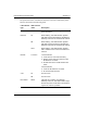
The operational status of the Remote Gateway 9150 unit is indicated by these
LEDs as described in the following table.
LED indicator
type
LED indicator
name Description
Power On When lit, this LED indicator signifies that
power is present.
Ethernet TX When flashing, this LED indicator signifies
that data is being transmitted by the Remote
Gateway 9150 unit over the Ethernet network.
RX When flashing, this LED indicator signifies
that data is being presented to the Remote
Gateway 9150 unit over the Ethernet network.
COLL When flashing, this LED indicator signifies
that a collision has occurred on the Ethernet
network.
Module L1 and L2 L1 LED indicator:
! not lit: there is no D-channel activity
! flashing: the D-channel is active but the
B-channel is not active
! lit solid: both the D- and B-channels are
active
L2 LED indicator:
! not lit: the B-channel is not active
! lit: the B-channel is active
V.35 TX For future use.
RX For future use.
Boot status Status Indicates the condition of the Remote
Gateway 9150 unit. This LED indicator stays
lit when the power on self-test is successful. If
it goes out, there is a problem.