
User manual


94 Remote Gateway 9150 Installation and Administration Guide
Installing the Remote Gateway 9150 unit Standard 3.1
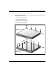
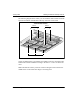
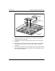
Determining where to install the modules
Each module position is labeled on the Remote Gateway 9150 unit circuit board
as shown in the following table:
Module type Valid module positions
DSP application module ! MOD 1
! MOD 2
! MOD 3
Trunk interface module Telco 1 connector (phone lines 1 through 16):
! MOD 4
! MOD 5
Trunk interface module
(continued)
Telco 2 connector (phone lines 17 through 32):
! MOD 6
! MOD 7
Note: Each Telco connector provides access to
two ISDN BRI lines (each with two B-channels).