
User manual


10 Low-speed ATM configuration
Nortel Secure Router 8000 Series
Configuration -WAN Access
10-38 Nortel Networks Inc. Issue 5.3 (
30 March 2009)
10.12.1 Example for configuring IPoA
Networking requirements
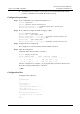
In Figure 10-3, connect routers A, B and C to the ATM network. All the PVCs on ATM
interfaces of the three routers use IPoA application mode.
Figure 10-3 Networking diagram for IPoA configuration
RouterA
RouterB
RouterC
IP:202.38.160.1/24
To B: 0/40
To C: 0/41
Interface: ATM 1/0/0
IP:202.38.160.2/24
To A: 0/50
To C: 0/51
Interface: ATM 1/0/0
IP:202.38.160.3/24
To A: 0/60
To B: 0/61
Interface: ATM 1/0/0
ATM
network
Configuration roadmap
The configuration roadmap is as follows:
1. Create the PVC of ATM interfaces on each router.
2. Specify the protocol to bear the IP protocol.
Data preparation
To configure IPoA, you need the following data:
z
The IP addresses of the ATM interfaces of the three routers are 202.38.160.1,
202.38.160.2 and 202.38.160.3 respectively.
z
In ATM network, the VPI/VCI of Router A is 0/40 and 0/41, connecting with Router B
and Router C respectively.
z
The VPI/VCI of Router B is 0/50 and 0/51, connecting with Router A and C respectively.
z
The VPI/VCI of Router C is 0/60 and 0/61, connecting with Router A and B respectively.
Configuration procedure
Step 1 Configure Router A.
# Enter the ATM interface view, and configure an IP address for it.
<RouterA> system-view
[RouterA] interface atm 1/0/0