
User manual


Nortel Secure Router 8000 Series
Configuration -WAN Access 10 Low-speed ATM configuration
Issue 5.3 (
30 March 2009) Nortel Networks Inc. 10-7
The segment point is defined in I.610. One ATM link may consist of many segments.
The segment points can terminate all the segment cells but not the end cells. If the
segment points detect that the link is faulty, they insert the end Alarm Indication Signal
(AIS) cells into the downstream nodes and the segment RDI cells into the upstream
nodes.
z
Middle point
The middle point is in between the two segment points or the two end points, so it can be
classified into two types: end middle point and segment middle point. The middle points
do not terminate any cells, and the segment cells and end cells can be transmitted
transparently. If the middle points detect that the link is faulty, they send the segment
AIS cells and end AIS cells to the downstream nodes.
The nodes having the different OAM attributes process the AIS/RDI cells differently and
indicate the information about the faults occurring in the ATM layer or the physical layer
to implement the fault management.
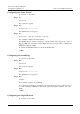
Figure 10-2 shows the working principles.
Figure 10-2 Working schematic diagram of the AIS/RDI cells
end-point
AIS
seg-point
node 1 node 2
seg-middle
node 3
SEG-RDI
E2E -AIS
E2E-RDI
E2E -AIS
E2E-RDI
E2E -AIS
E2E-RDI
seg-point
node 4
end-point
node 5
E2E-RDI
RDI
After the node 2 is detected to be faulty, the following operations are produced:
1. The node 2 inserts the E2E-AIS cells to the downstream node 3 and inserts the SEG-RDI
cells to the upstream node 1.
2. When receiving the SEG-RDI cells, the node 1 terminates the cells. When receiving the
E2E-AIS cells, the node 3 transparently transmits the cells to the downstream node 4.
3. When receiving the E2E-AIS cells, the node 4 transparently transmits the cells to the
downstream node 5.
4. When receiving the E2E-AIS cells, the node 5 terminates the cells and inserts the
E2E-RDI cells to the upstream node 4.
5. The E2E-RDI cells are transmitted to the node 1 passing through node 4, node 3, and
node 2.
6. When receiving the E2E-RDI cells, the node 1 terminates the cells.
Finally, the node 5 receives the information about the upstream faults. The node 1 receives the
information about the downstream faults.