
User manual


Nortel Secure Router 8000 Series
Configuration -WAN Access 10 Low-speed ATM configuration
Issue 5.3 (
30 March 2009) Nortel Networks Inc. 10-3
10.1 Introduction
This section covers the following topics that you need to know before you configure ATM:
z
ATM protocol stack
z
ATM interface
z
ATM OAM
z
ATM applications
z
references
10.1.1 ATM protocol stack
Asynchronous Transfer Mode (ATM) is the transmission and switching mode for broadband
ISDN services by the International Telecommunication Union - Telecommunication
Standardization Sector (ITU-T) in June, 1992. Because of its high flexibility and its capability
for supporting the multi-media service, ATM is considered as the key to realize broadband
communications.
As defined by ITU-T, ATM implements transmission and switching of data based on cells. An
ATM cell has a fixed length of 53 bytes. The first 5 bytes make up the cell header that
contains the cell routing and priority information. The remaining 48 bytes are used for
payloads.
ATM is connection-oriented. Each virtual circuit (VC) is identified by a Virtual Path Identifier
(VPI) and a Virtual Channel Identifier (VCI) together. One VPI/VCI value has local
significance on a segment of the link between ATM nodes. When you release a connection,
the relevant VPI/VCI values are also released.
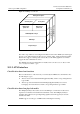
The ATM protocol architecture has the following three planes:
z
User Plane
z
Control Plane
z
Management Plane
User Plane and Control Plane are divided into four layers respectively:
z
Physical Layer
z
ATM Layer
z
ATM Adaptation Layer (AAL)
z
Upper Layer
Each layer is further divided into several sub-layers.
The Control Plane uses signaling protocols to establish and release connections.
Management Plane is divided into Layer Management and Plane Management.
z
Layer Management: manages all the layers in each plane. It has a layered structure
corresponding to other planes.
z
Plane Management: performs system management and communication between different
planes.
The relationships among layers and planes are shown in
Figure 10-1.