
User manual


9 HDLC configuration
Nortel Secure Router 8000 Series
Configuration -WAN Access
9-6 Nortel Networks Inc. Issue 5.3 (
30 March 2009)
9.4.1 Example for configuring HDLC
Networking requirements
Connect Router A and Router B by the POS interface, and t require them to run HDLC.
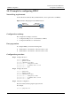
Figure 9-1 Networking diagram of the HDLC functions
RouterA RouterB
POS1/0/0
100.1.1.1/24
POS1/0/0
100.1.1.2/24
Configuration roadmap
The configuration roadmap is as follows:
1. Configure the link protocol of each interface to HDLC.
2. Configure the IP address of each interface.
Data preparation
To configure DHCP, you need the following data:
z
The IP address of the interface on Router is 100.1.1.1/24.
z
The IP address of the interface on Router is 100.1.1.2/24.
Configuration procedure
Step 1 Configure Router A.
<Nortel> system-view
[Nortel] sysname RouterA
[RouterA] interface pos 1/0/0
[RouterA-Pos1/0/0] link-protocol hdlc
[RouterA-Pos1/0/0] ip address 100.1.1.1 24
[RouterA-Pos1/0/0] quit
Step 2 Configure Router B.
<Nortel> system-view
[Nortel] sysname RouterB
[RouterB] interface pos 1/0/0
[RouterB-Pos1/0/0] link-protocol hdlc
[RouterB-Pos1/0/0] ip address 100.1.1.2 24
[RouterB-Pos1/0/0] quit
Step 3 Verify the configuration.
Router A and Router B can ping through each other.
For example.
[RouterA] ping 100.1.1.2