
User manual


Nortel Secure Router 8000 Series
Configuration -WAN Access 8 Frame relay configuration
Issue 5.3 (
30 March 2009) Nortel Networks Inc. 8-69
#
interface Tunnel2/0/1
source 10.120.20.2
destination 10.120.20.1
#
return
8.14.8 Example for configuring the frame relay frf9 compression
Networking requirements
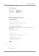
As shown in Figure 8-11, connect Router A and Router B over the FR network and FR frf9
enable compression between them.
Figure 8-11 Networking diagram of FR compression
Router A Router B
Serial4/0/0
10.110.40.1/24
Serial4/0/0
IP:10.110.40.2/24
Frame relay
network
DLCI=100 DLCI=100
Configuration roadmap
The configuration roadmap is as follows:
1. Configure the link protocol on each interface to FR.
2. Configure the working mode of each interface.
3. Configure the IP addresses on interfaces and the VC number of each network segment.
4. Configure the FR compression.
Data preparation
To configure the FR compression, you need the following data:
z
The IP address on each interface is shown in Figure 8-11
z
The VC number of two network segments is 100
z
The interfaces of two routers work in the DTE mode
Configuration procedure
Step 1 Configure Router A.
<RouterA> system-view
[RouterA] interface serial 4/0/0
[RouterA-Serial4/0/0] ip address 10.110.40.1 255.255.255.0
[RouterA-Serial4/0/0] link-protocol fr
[RouterA-Serial4/0/0] fr interface-type dte
[RouterA-Serial4/0/0] fr dlci 100
[RouterA-fr-dlci-Serial4/0/0-100] quit
[RouterA-Serial4/0/0] fr map ip 10.110.40.2 100 compression frf9