
User manual


8 Frame relay configuration
Nortel Secure Router 8000 Series
Configuration -WAN Access
8-66 Nortel Networks Inc. Issue 5.3 (
30 March 2009)
8.14.7 Example for configuring frame relay over IP
Networking requirements
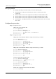
As shown in Figure 8-10, you connect two FR networks through Router A and Router B.
Enable the FR over IP function on Router A and Router B to connect two FR networks over
an IP network.
Figure 8-10 Networking diagram of FR over IP
RouterA RouterB
DLCI 300
DLCI 100
DLCI 200 DLCI 200
Frame relay
network
Frame relay
network
Serial 1/0/0
Serial 1/0/0
Serial 2/0/0
10.120.20.1/24
Serial 2/0/0
10.120.20.2/24
Tunnel 2/0/1
10.120.21.5/24
Tunnel 2/0/1
10.120.21.3/24
Tunnel
IP network
Configuration roadmap
The configuration roadmap is as follows:
1. Configure the link protocol to FR.
2. Enable the FR switching in Router B and Router C globally.
3. Configure the working mode and the IP address of each interface and the VC number of
each network segment.
4. Configure the Tunnel interface.
5. Configure the FR over IP function.
Data preparation
To configure the FR over IP function, you need the following data:
z
The VC number of each network segment is shown in Figure 8-10
z
The IP address of Serial 2/0/0 on Router A is 10.120.20.1/24
z
The IP address of Serial 2/0/0 on Router B is 10.120.20.2/24
Configuration procedure
Step 1 Configure Router A.
# Enable the FR switching.
<RouterA> system-view
[RouterA] fr switching