
User manual


Nortel Secure Router 8000 Series
Configuration -WAN Access 8 Frame relay configuration
Issue 5.3 (
30 March 2009) Nortel Networks Inc. 8-59
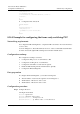
Figure 8-8 Networking diagram of PVC standby groups of FR switching
Serial2/0/0
DLCI 200
SGSN 1
RouterA
Serial3/0/0
DLCI 300
SGSN 2
Serial1/0/0
Basic station
controller
PVC 1
PVC 2
DLCI 100
Configuration roadmap
The configuration roadmap is as follows:
1. Configure the link protocol to FR.
2. Enable the FR switching in the global mode.
3. Configure the VC number of each network segment.
4. Configure the working mode of each interface.
5. Configure the active PVC and the standby PVC.
Data preparation
To configure the PVC standby of the FR switching, you need the following data:
z
The VC number of each network segment is shown in Figure 8-8.
z
The serial interfaces on Router A work in the DCE mode.
Configuration procedure
Step 1 Configure Router A.
# Enable the FR switching on Router A.
<RouterA> system-view
[RouterA] fr switching
# Encapsulate Serial 1/0/0, Serial 2/0/0 and Serial 3/0/0 with the FR protocol.
[RouterA] interface serial 1/0/0
[RouterA-Serial1/0/0] link-protocol fr
[RouterA-Serial1/0/0] fr interface-type dce
[RouterA-Serial1/0/0] fr dlci 100
[RouterA-fr-dlci-Serial1/0/0-100] quit
[RouterA-Serial1/0/0] quit
[RouterA] interface serial 2/0/0
[RouterA-Serial2/0/0] link-protocol fr