
User manual


Nortel Secure Router 8000 Series
Configuration -WAN Access 7 LAPB and X.25 configuration
Issue 5.3 (
30 March 2009) Nortel Networks Inc. 7-69
7.8.10 Example for configuring the X.25 load balancing carrying IP
Datagrams
Networking requirements
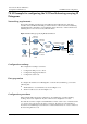
X.25 packet switching networks interconnect IP networks in different areas. The X.25
networks carries the IP data. The ISPs provide the function of X.25 network load balancing
and implement the configuration of load balancing at the client end, to achieve the line load
balancing when a server is accessed by different clients.
Figure 7-19 X.25 hunt group carrying IP data transmission
RouterA
1111
Server B
10.3.1.3/24
Server A
10.3.1.2/24
Eth2/0/0
10.1.1.1/24
RouterB
2222
Eth2/0/0
10.2.1.1/24
serial1/0/0
1.1.1.1/24
serial1/0/0
1.1.1.2/24
PC A
10.1.1.2/24
PC B
10.2.1.2/24
Eth2/0/0
10.3.1.1/24
serial1/0/0
1.1.1.3/24
RouterC
3333
serial1/0/1
2.1.1.3/24
X.25 packet
Switching
network
Configuration roadmap
The configuration roadmap is as follows:
1. Configure the link protocol to X.25.
2. Configure the mapping information.
3. Configure the static route.
Data preparation
To configure the transmission of IP datagrams over the X.25 load balancing, you need the
following data:
z
The IP addresses of each interface are shown in Figure 7-19.
z
The X121 addresses are shown in Figure 7-19.
Configuration procedures
In this example, ISP performs the configuration of load balancing on packet switching
exchange. You need to implement only the common X.25 configuration on routers.
Note that the user must configure a virtual IP address and two static routes on interface Serial
1 to "deceive" the router because two lines connected to the same peer exist in Router C.
You achieve load balancing because Router C considers that there are two routes connected to
the network segment 10.1.1.0.