
User manual


Nortel Secure Router 8000 Series
Configuration -WAN Access 7 LAPB and X.25 configuration
Issue 5.3 (
30 March 2009) Nortel Networks Inc. 7-65
7.8.9 Example for configuring the X.25 load balancing
Networking requirements
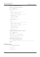
Configure hunt group on Router A which serves as an X.25 switch. Simultaneously, enable the
function of substitution between destination addresses and source addresses, so that the calls
of X.25 terminal can be sent to Router B, Router C, and Router E to achieve load balancing.
As an X.25 switching exchange, Router D performs the XOT function and connects Router A
and Router E. Router B, Router C, and Router E are DTEs in a hunt group. They provide X.25
terminals with identical services.
Figure 7-18 Networking diagram of typical configuration of X.25 hunt group
X.25 Terminal
X.25 Terminal
X.25 Terminal
1111
1112
1119
Serial2/0/0
S
er
i
a
l
1
/
0/
0
Serial2/0/1
E
t
h
4
/
0
/
0
1
0
.
1
.
1
.
1
/
2
4
Serial1/0/0
Ser
ial1
/
0/0
E
t
h
2
/
0
/
0
1
0
.
1.
1
.
2
/
2
4
RouterA
RouterB
RouterC
RouterD RouterE
8888
8888
8888
Serial1/0/0
Serial1/0/0
huntgroup 2222
S
er
i
a
l
3
/
0/
0
S
erial1
/
0/1
Configuration roadmap
The configuration roadmap is as follows:
1. Configure the link protocol to X.25.
2. Configure the X.25 switching.
3. Configure the hunt group.
4. Configure the switching route.
Data preparation
To complete the configuration, you need the following data:
z
The IP address of the Ethernet interface 4/0/0 on Router A is 10.1.1.1/24.
z
The IP address of the Ethernet interface 2/0/0 on Router D is 10.1.1.1/24.
z
IP addresses of the interfaces as shown in Figure 7-18
Configuration procedure
Step 1 Configure Router A.