
User manual


Nortel Secure Router 8000 Series
Configuration -WAN Access 7 LAPB and X.25 configuration
Issue 5.3 (
30 March 2009) Nortel Networks Inc. 7-59
[RouterC] x25 switch svc 2 interface serial 2/0/0
# Configure the XOT switching.
[RouterC] x25 switch svc 1 xot 10.1.1.1
# Configure Ethernet 1/0/0.
[RouterC] interface ethernet 1/0/0
[RouterC-Ethernet1/0/0] ip address 10.1.1.2 255.0.0.0
[RouterC-Ethernet1/0/0] quit
# Configure Serial 2/0/0.
[RouterC] interface serial 2/0/0
[RouterC-Serial2/0/0] link-protocol x25 dce ietf
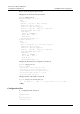
Step 5 Verify the configuration.
The two hosts can ping through each other.
# Consider the information about the XOT state and configuration on Router B as an example.
[RouterB] display x25 xot
SVC 1024: ( ESTAB )
tcp peer ip: 10.1.1.2, peer port: 1998
tcp local ip: 10.1.1.1, local port: 60115
socket keepalive period: 5, keepalive tries: 3
come interface name: Serial1/0/0-10.1.1.2-1024
go interface name: Serial1/0/0
# Display the VC information of Router B.
[RouterB] display x25 vc
Interface: Serial2/0/0-10.1.1.2-1024
SVC 1024
State: P4
XOT SVC <--> Serial2/0/0 SVC 1024
Window size: input 2 output 2
Packet Size: input 128 output 128
Local PS: 0 Local PR: 0 Remote PS: 0 Remote PR: 0
Local Busy: FALSE Reset times: 0
Input/Output:
DATA 10/10 INTERRUPT 0/0
RR 0/1 RNR 0/0 REJ 0/0
Bytes 840/840
Snd Queue(Current/Max): 0/200
Interface: Serial2/0/0
SVC 1024
State: P4
SVC <--> XOT Serial2/0/0-10.1.1.2-1024 SVC 1024
Window size: input 2 output 2
Packet Size: input 128 output 128
Local PS: 0 Local PR: 0 Remote PS: 0 Remote PR: 0
Local Busy: FALSE Reset times: 0
Input/Output:
DATA 10/10 INTERRUPT 0/0
RR 1/0 RNR 0/0 REJ 0/0
Bytes 840/840