
User manual


7 LAPB and X.25 configuration
Nortel Secure Router 8000 Series
Configuration -WAN Access
7-16 Nortel Networks Inc. Issue 5.3 (
30 March 2009)
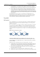
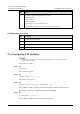
Figure 7-7 X.25 channel division
1
LTC
LIC
HTC
HIC
LOC
HOC
4095
PVC range
Incoming-only channel range
unused
Two-way channel range
unused
Outgoing-only channel range
unused
1
LTC
LIC
HTC
HIC
LOC
HOC
4095
PVC range
Incoming-only channel range
unused
Two-way channel range
unused
Outgoing-only channel range
unused
For the meanings of these six parameters, refer to Table 7-1.
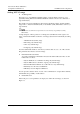
Table 7-1 Description of X.25 channel range delimitation parameters
Parameter Description
LIC Lowest Incoming-only Channel
HIC Highest Incoming-only Channel
LTC Lowest Two-way Channel
HTC Highest Two-way Channel
LOC Lowest Outgoing-only Channel
HOC Highest Outgoing-only Channel
Each range (except PVC ranges, it is 1 to (lic-1)) is defined by two parameters respectively
working as upper limit and lower limit. The parameters are in the range of 1 to 4095
(including 1 and 4095). The parameters are correct only if the following conditions are met:
− In strict ascending order, i.e. 1 ≤ lic ≤ hic < ltc ≤ htc < loc ≤ hoc ≤ 4095.
− If the upper limit (or lower limit) of a range is 0, then the lower limit (or upper limit)
shall also be 0, (which indicates this range is disabled to use).
Note the following points:
− On the two sides (DTE and DCE) of a physical connection, these six parameters of
X.25 must be symmetric, as different settings at the two sides may result in an
improper procedure and cause transmission failures.
− You should first set the range of the unidirectional call in channel, then set the range
of bidirectional call-in channel, and finally set the range of unidirectional call-out
channel.
− In the configuration process, you should determine to implement the correct settings
of parameters. (Pay attention to the default settings of each parameter on the basis of
assuring an ascending order.)