
User manual


Nortel Secure Router 8000 Series
Configuration -WAN Access 5 Logical interface configuration
Issue 5.3 (
30 March 2009) Nortel Networks Inc. 5-17
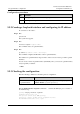
Figure 5-1 Networking diagram of configuring the sub-interface
Ethernet 3:
129.11.0.0/24
Ethernet 2:
129.10.0.0/24
DLCI=50
DLCI=60
DLCI=70
DLCI=80
202.38.160.1
202.38.161.2
202.38.161.1
202.38.160.2
RouterA
Router B
RouterC
Ethernet 1:
129.9.0.0/24
Serial1/0/0
Frame Relay
network
Configuration roadmap
The configuration roadmap is as follows:
1. Configure link protocol of the interface that accesses the FR network to FR.
2. Configure sub-interfaces and allocate IP addresses and VC.
3. Configure the static route to the opposite LAN.
Data preparation
To configure the sub-interface, you need the following data:
z
On Router A, the number of the interface that accesses the FR network is Serial 1/0/0:0.
z
IP addresses of two sub-interfaces on Router A are 202.38.160.1 and 202.38.161.1
respectively.
z
DLCIs that connect Router A to the FR network are 50 and 60 respectively.
z
Network addresses of three LANs are shown in Figure 5-1.
z
On Router B and Router C, the IP addresses of the interfaces that access the FR network
are 202.38.160.2 and 202.38.161.2 respectively.
Configuration procedure
Step 1 Configure Router A.
# Configure link layer protocol as FR on Serial 1/0/0:0 of Router A.
<RouterA> system-view
[RouterA] interface serial 1/0/0:0
[RouterA-Serial1/0/0:0] link-protocol fr
[RouterA-Serial1/0/0:0] quit