
User manual


Installing and Maintaining the Versalar Switch Router 15000
3-4
308684-B Rev 00
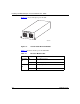
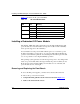
Table 3-2 describes the AC power unit LEDs.
Table 3-2. AC Power Module LEDs
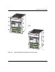
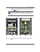
Installing a Redundant DC Power Module
The Versalar 15000 ships with a single DC power module installed in the right
power module slot. You can install a second power module for DC redundancy
and to provide support for AC redundancy.
You can install a second power module with the power on or off. If two power
modules are installed, you can remove one power module without affecting the
operation of the hardware platform. You should replace the failed power module
as soon as possible to restore high-availability operation.
The operating system generates an event message in response to any change in the
status of a power module. These messages identify the power module by its slot.
From the front of the Versalar 15000, power module slot 1 is on the left, and
power module slot 2 is on the right.
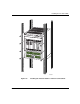
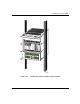
Removing and Replacing the Front Bezels
To access the DC power supplies, you must remove the bottom front bezel.
To remove the top or bottom front bezel:
1.
Using both hands, pull the bottom of the bezel forward (Figure 3-3).
2.
Remove the bezel from the chassis.
LED State Meaning
AC Good Off No input is present.
On (green) AC input is present.
Fail Off No problems.
On (Red) DC output has failed.
Pwr Good Off No output is present.
On (green) DC output is normal.