
User manual

Versalar 15000 Hardware Description
308684-B Rev 00
1-3
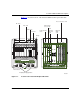
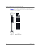
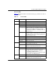
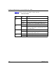
Figure 1-1 shows the location of the Versalar 15000 customer-replaceable units
(CRUs).
Figure 1-1. Location of the Customer-Replaceable Units
VRS0002A
12
11
10
9876
5
4
3
2
1
Access interface cards
SSP interface
console card
Optional
ARM
card
SSP
interface
Ethernet
card
Trunk interface
cards
Interface cards
Rear of chassis
VERSARLAR Switch Router 15000
Fan tray
AP cards
IFP cards
SSP cards
TP cards
12 345 6
7
8 9 10 11 12
Front of chassis
DC-input power supply modules
Processor cards