
User manual


Installing and Maintaining the Versalar Switch Router 15000
4-34
308684-B Rev 00
2.
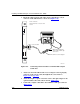
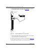
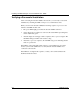
Insert the 9-pin receptacle end of the console cable (Order No. 110307)
into the modem connector on the SSP card (Figure 4-21)
.
Figure 4-21. Connecting a Modem to the Versalar 15000
3.
Insert the 25-pin plug connector at the other end of the console cable into
the modem’s RS-232 data communications port.
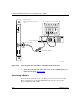
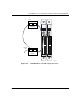
Two SSP cards, each with a modem, can share the same dial-up line (Figure 4-22)
.
The data terminal ready (DTR) signal on the modem port follows the active SSP
card. Only the modem that is attached to the active SSP card answers the phone.
BAC0043A
Pwr
Modem
Stat Run Mstr
3210
Temp Fan Maj Min
Diag Test Count
SSP
32
SQUEEZE TO REMOVE
Boot Flash
1
Option Cards
SQUEEZE TO REMOVE
Front of chassis
SSP card
slot 9 or 10
PHONE
DWR
(LEASE
3810
(LEASED)
3810
NMS
DIAL
Console cable