
User manual


Installing and Maintaining the Versalar Switch Router 15000
4-30
308684-B Rev 00
2.
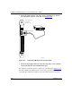
Insert the 9-pin receptacle end of the console cable into the console
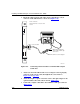
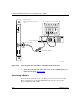
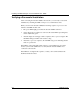
connector on the SSP interface console card (Figure 4-19)
.
Figure 4-19. Connecting a Console Cable to a Terminal with a 25-pin
Comm Port
3.
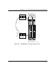
Attach one end of the null modem crossover adapter to the 25-pin plug
connector on the console cable, then tighten the screws. Refer to
Figure 4-18
on page 4-28.
4.
Attach the 25-pin receptacle end of the console cable-plus-adapter to the
optional standard AT serial cable, if desired (Figure 4-19)
.
5.
Connect the complete cable unit to the terminal’s comm port connector
(Figure 4-19)
.
COMM
20 mA PR
KB
VRS0143A
Rear of chassis
SSP-C interface console card
slot 10
Console cable
Pwr
SSP Interface
Cosole
Min
Maj
Mute
Alarm
Alarm
Console
Min NO
Min COM
Min NC
Maj NO
Maj COM
Maj NC
Alarm
Null modem crossover adapter
Optional standard AT
serial cable with 25-pin
connectors