
User manual


Installing and Maintaining the Versalar Switch Router 15000
4-2
308684-B Rev 00
Location of the Processor and Interface Cards
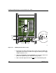
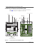
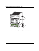
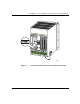
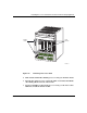
Figure 4-1 shows the location of the processor and interface cards. Refer to
Chapter 1 for descriptions of configurations of these cards.
Figure 4-1. Location of the Processor and Interface Cards
VRS0002A
12
11
10
9876
5
4
3
2
1
Access interface cards
SSP interface
console card
Optional
ARM
card
SSP
interface
Ethernet
card
Trunk interface
cards
Interface cards
Rear of chassis
VERSARLAR Switch Router 15000
Fan tray
AP cards
IFP cards
SSP cards
TP cards
12 345 6
7
8 9 10 11 12
Front of chassis
DC-input power supply modules
Processor cards